
Cialis ist bekannt für seine lange Wirkdauer von bis zu 36 Stunden. Dadurch unterscheidet es sich deutlich von Viagra. Viele Schweizer vergleichen daher Preise und schauen nach Angeboten unter dem Begriff cialis generika schweiz, da Generika erschwinglicher sind.
Cyclodextrin and bile salt interactions using isothermal titration calorimetry
Cyclodextrin and Bile Salt Interactions
Using Isothermal Titration Calorimetry
Paula Melo Paulon Hansen
Thomas Allan Rayner
Supervisor: Peter Westh, Christian Schonbeck
International Bachelor Studies in Natural Science
Roskilde University, Fall 2009
Firstly, we would like to express our gratitude to Peter Westh and Christian Schönbeck for their assistance, guidance and advice as our supervisors and to Lundbeck for providing us with the different chemicals used in our experiments.
We would also like to thank Ph.D. students Leigh Murphy and Søren Nymand Olsen for their time and advice helping us with using ITC and ORIGIN; and thanks to Morten F. Pedersen for giving advice concerning statistical analysis for our project.
Finally, we appreciate all who directly and indirectly helped us with our experiments and project writing.
Cover figure – ITC experiment with β–CD and GCDC at 25oC, replica 1.
Background: the capability of cyclodextrins of forming complexes with different substrates in aqueous solution, improving consequently the solubility of such compounds, has aroused the attention from the pharmaceutical industry. Cyclodextrins are cyclic oligosaccharides, mainly made up of 6 to 8 glycopyranose units and they can be found in nature or can be artificially synthesized.
Purpose: the aim of this project is to investigate the interaction between 2 kinds of cyclodextrins -β-cyclodextrin and hydroxypropyl-0.6-β-cyclodextrin- with 3 kinds of bile salts - glycocholate (GC), glycodeoxycholate (GDC) and glycochenodeoxycholate (GCDC), using isothermal titration calorimetry (ITC) and determine the binding constants and thermodynamics parameters for each different cyclodextrin and bile salt combination under different temperatures: 25, 30, 40 and 50 oC. The lowest temperature was chosen based on what has been previously cited in the literature, while the highest temperatures were meant to test the interaction of cyclodextrins and bile salts in the highest temperature range possible using ITC.
Results: The interaction of cyclodextrins and bile salts presented a 1:1 binding relation. The binding constant for GCDC and both cyclodextrins were highest when compared to the other bile salts. The entropy and enthalpy changes for all the interactions between bile salts and cyclodextrins decreased with increased temperature. The standard Gibbs free energy has not changed significantly when going from 25°C to 50°C for each interaction, which indicates enthalpy-entropy compensation.
Conclusions: Our data and analysis suggest that β-cyclodextrin binds stronger to GC and GCDC than hydroxypropyl-0.6-β-cyclodextrin does. GCDC binds strongest and this may be due to the absence of a hydroxyl group on C12 (C-ring of the bile salt) which makes the bile salt more hydrophobic and thus increases the binding constant (K) and decreases the heat capacity change (∆Cp) of the interaction and therefore also the change in the accessible surface area (∆ASA). Hydrophobic hydration may be the reason for the entropy-enthalpy compensation that has been observed when temperature increases.
Table of contents
Since 1891, when cyclodextrins (CD) were first described by A. Villiers (Coly and Aaron, 1998 p.129), interest has continually grown for the usage of different applications, especially within the pharmaceutical industry for using cyclodextrins for drug administration. This is due to the CD ability to form aqueous complexes with other chemical compounds, whether they are organic or inorganic.
CDs are also known as cyclo oligosaccharides and consist of α-1,4-D-glucose units, which are formed by the breakdown of starch by enzyme amylase of
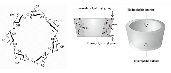
B. Macerans (Cameron and Cooper, 2002 p. 279). They are bonded together to form a cone shaped molecule where the interior part of the cone is hydrophobic and the exterior part is hydrophilic. This presents the CD with the ability to contain a guest molecule inside its cone structure that is otherwise insoluble in an aqueous solution and still be able to dissolve in water. This ability leads to the drug administration application.
In order for the guest molecule to be removed from the CD's interior it can be out-competed by another molecule, which in this case are bile salts (BS). These molecules are water-soluble steroids and play an important role in the absorption and digestion of lipids and lipid-soluble vitamins. Bile salts are found in the duodenum and since they are water-soluble, and are thereby impermeable to the cell membranes, the high concentration of these BS facilitates the formation of micelles for lipid absorption (Stamp and Jenkins, 2008 p. 1-3).
Due to the BS good ability to interact with certain molecules in our digestive system it is of great interest to understand the binding dynamics between CDs and BS. Such studies have been done before, though they seem to focus on the reaction of certain chemicals and molecules. This study concentrates on the complexation of the most common CDs and BS under different temperatures (25, 30, 40 and 50ºC) and is monitored by using Isothermal Titration Calorimetry (Microcal VP-ITC). This can give us an understanding on whether there is a change in binding behaviour between CDs and BS when the temperature is increased.
2. Theoretical Part
Figure 1: Molecular structure of the 3 most naturally occurring CDs: α-, β- and γ- CD.
(http://www.chemiedidaktik.uni-wuppertal.de/disido_cy/cyde/info/03_physical_cy.htm)
Cyclodextrins are cyclic oligosaccharides (Ollila
et al. 2001 and Loftsson
et al. 1996) which are mainly composed of 6, 7 or 8 glucopyranoses (called α-, β- and γ- CD, respectively) that are connected by α-1,4 glycosidic bonds (Uekama
et al. 1998). They are produced from the action of the enzyme amylase of
Bacillus macerans in starch (Bender
et al. 1978). Cyclodextrins contain a hydrophilic outside and a hydrophobic interior which is of great interest to the pharmaceutical industry as some hydrophobic drug molecules can bind to the interior of the CDs forming complexes. By doing so, an enhancement of the solubility and bioavailability of some drug molecules can be observed (Uekama
et al. 1998). The water solubility of α-, β- and γ-CDs and the differences among them are showed in table 1. The solubility of the β-CD is the lowest among those three CDs and it can be explained by the formation of strong hydrogen bonds between two adjacent glucopyanose units of the β-CD (Szejtli, 1998). Substitution of the hydrogen of the hydroxyl groups of this CD by methyl, ethyl, among other groups, can enhance its solubility (Loftsson
et al. 1996 and Loftsson
et al. 2004). Hydroxypropyl-β-CD (HPβCD) can increase its aqueous solubility by up to 60% or more (Davis
et al. 2004). The solubility of α- and γ- CDs are higher than the one observed in β-cyclodextrins: less hydrogen bonds are formed in α-cyclodextrins than it is expected; while γ- cyclodextrins have more flexible structures which are the explanation for the higher solubility (Szejtli, 1998). This report focuses on natural β-CD and on HP-0.6-β-CD, which together with other hydroxypropylated β- and γ-cyclodextrins are the main kind of cyclodextrins used as drug carriers (Szejtli, 1998). The 0.6 on hp-0.6.CD is related to the number of hydroxylpropyl groups present per cyclodextrin unit (Buvári-Barcza et
al 1994). Table 1 below shows some differences among α-, β- and γ-CDs.
Central cavity diameter (Å)
Water solubility at 25 °C (g/100 mL)
Table1 : Characteristics of α-, β- and γ- cyclodextrins (modified from Loftsson et al. 1996).
Figure 2: Chemical structure of β-CD. R can be substituted by different radicals forming derivatives of β-CDs
(table 2) (http://www.chemiedidaktik.uni-wuppertal.de/disido_cy/cyde/info/01_manufacture_cy.htm)
β-Cyclodextrin
-CH2CH2OH or -H
-CH2CHOHCH3 or -H
Randomly methylated β-cyclodextrin
-CH3 or -H
Glucosyl or maltosyl group
Table 2: Derivatives of β-cyclodextrin (Modified from Loftsson 2004).
Trade Name
Table 3: Examples of products in the market containing β-CD and derivatives (modified from Loftsson, 2004).
mation of complexes
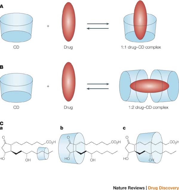
Cyclodextrins in aqueous solutions welcome "guest molecules", other than water, in their hydrophobic cavities (Szejtli, 1998). The interaction of a CD and a guest molecule has usually a molar ratio of 1:1, but other kinds of interactions can be found, as showed in figure 3 (Stella et al. 2008). This complex formation can then increase the solubility of some drug molecules (Stella et al. 2008 and Loftsson et al. 1996). Throughout the formation of complexes between cyclodextrins and drug molecules, no breakages of covalent bonds are noticed, but what leads to the formation of such complexes is the release of
water molecules from the cavity
Figure 3: Formation of complexes
(http://www.nature.com/nrd/journal/v3/n12/images/nrd1576-f3.jpg)
hydrogen bonding, among others (Loftsson 2004). Complexes formed by HP-0.6-β-CD and β-CD with some bile salts: glycocholate (GC), glycodeoxycholate (GDC) and glycochenodeoxycholate (GCDC) are the most relevant complexes for this report.
2.2. Bile Salts
Figure 4 : Cholesterol conversion to 7-hydroxy-Cholesterol (Stamp & Jenkins, 2008)
This section will explain the basic and important aspects of BS while also distinguishing the difference between what is known as BS and bile acid (BA).
When looking at the human digestive system, BS play a pivotal role in lipid digestion and absorption. The absorption of lipid soluble vitamins is also dependent on BS. These produce through various processes in the hepatocytes in the liver. Here, cholesterol is catabolized and converted into primary BA, which are Cholic Acid (CA) and Chenodeoxycholic Acid (CDCA), through the involvement of the 7 α-hydroxylase enzyme (CYP7A1), which happens in the liver.
Several other enzymes process the 7-hydroxy-cholesterol, converting it to mainly CA and CDCA. The enzyme 3-β-hydroxy-Δ5-C27-steroid dehydrogenase (HSD3B7) converts the 7-hydroxy-cholesterol to 7-hydroxy-4-cholesten-3-one. Thereafter, hydroxylation of 7-hydroxy-4-cholesten-3-one at the carbon 12 position is performed by sterol 12α-hydroxylase (CYP8B1), which thereby prompts the synthesis from CDCA to CA. Two other cytosolic enzymes, 4Δ-3-oxosteroid-5β-reductase (AKR1D1) and 3α-hydroxysteriod dehydrogenase (AKR1C4), perform a reduction of the double-bond and C27-hydroxylase (CYP27A1) oxidizes the carbon 27 on the side chain to a carboxylic acid (Monte et al. 2009, p. 807-808).
After the conversion of cholesterol to BAs, the BAs are thereafter conjugated to mainly either glycine or taurine, where the BAs are thereby transformed into BS. Glycine conjugated BAs are represent above 70% of the total bile in the human body, making it the most abundant form, where taurine conjugates represent above 20%, making these two conjugated BAs the most common acids that are involved in lipid digestion (Stamp and Jenkins, 2008 p. 1-9). These conjugated BAs have higher water solubility than their unconjugated forms. According to Alvaro et al. the tauro-, glyco-CD and tauro-, glyco-CDCA conjugates holds 9.4 (±0.8), 26.1 (±3.2), and 11.6 (±2.2), 31.9 (±3.4) percent of total bile salts in the human body, respectively. The bile samples were taken from 3 female subjects from the gall bladder through needle aspiration. The subjects were kept fasting for 12 hours before sampling and previous food intake was disregarded.
For the experiments in this report, three BS are used, which are all glycine conjugates. Figure 5 illustrates the three different BS, where Glycocholic Acid (GC) and Glycochendeoxycholic Acid (GCDC) which corresponds to glycol-CD and glycol-CDCA, respectively. Glycodeoxycholic Acid (GDC) is similar to GC, although its hydroxyl group on carbon 7 has been replaced with hydrogen. Another relevant issue to examine is the critical micellar concentration (CMC), due to a risk of the BS forming micelles during the experiments. According A. Roda et al. 1983, who measured the CMC through surface tension, estimated that micelles will form when GC, GDC and GCDC reaches concentrations of 12, 6 and 6 mM, respectively, in water and 10, 2 and 1.8 mM, respectively, in 15 mM Na+ solution. It would thereby be preferable to apply BS concentration below 1.8 mM to insure best possible results.
Glychodeoxycholic acid
Figure 5: Structure of glyco-conjugated BS and modified table with the different substitutions for the
different BS used in this report (modified from Holm et al. 2009).
3. Empirical Part
3.1. Isothermal Titration Calorimetry
For the experiments presented in this report isothermal titration calorimetry (ITC) machine MicroCal was used.
Calorimetry is a general method to obtain thermodynamic information of a reaction for all physical, biological and chemical processes that involve heat exchange. ITC is used for obtaining information about binding of molecules at constant temperature (Saboury, 2004). ITC monitors the heat changes and yields thermodynamic information about the reaction, such as the enthalpy change (ΔH°), the association constant (K-value) and the stoichiometry of binding (Saboury, 2004, Ollila et al. 2001). Having this information, it is possible to calculate also free energy of binding (ΔGo) and the entropy change (ΔSo). So far, calorimetry is the only direct method to determine the enthalpy of binding (Ollila et al. 2001, Ladbury and Chowdhry, 1996).
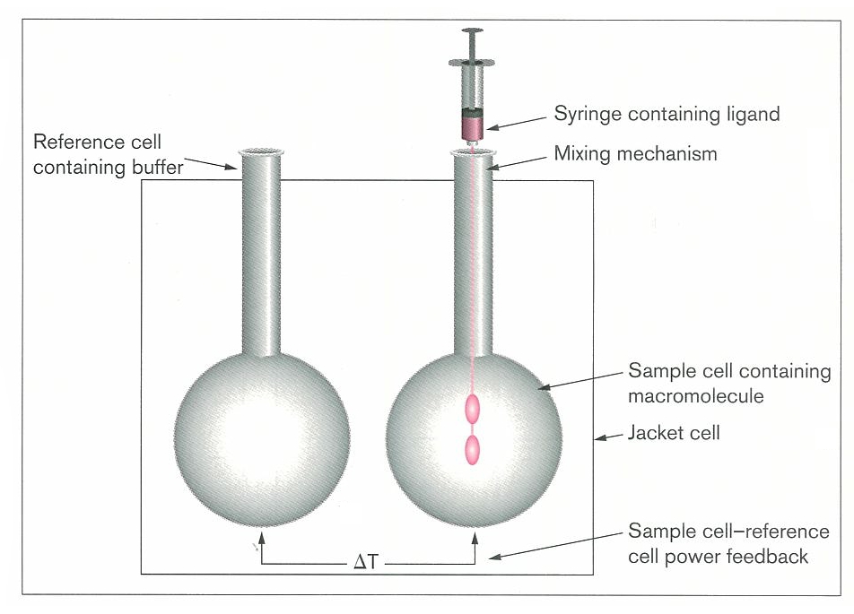
Figure 6 shows a schematic diagram of an ITC instrument. It consists of two identical cells: one containing a reference sample (buffer or water) and the other containing the sample. The cells are in an isothermal jacket where heat is applied so that both cells would be at the desired temperature and thermal equilibrium. The principle of calorimetry experiments is measuring the heat of interaction of two components by titration of one reactant (ligand) into a solution that contains the other reactant (macromolecule). So after each
Figure 6: The schematic illustration of ITC instrument (Ladbury addition a reaction occurs and some
and Chowdhry, 1996)
amount of heat is absorbed or released. Thereby, the calorimeter measures the heat energy per unit time (μcal s-1) that must be applied to the sample cell to keep both cells in equilibrium (ΔT remains constant). The heat absorbed or released indicates whether the ongoing reaction is endothermic or exothermic, respectively. The two reacting molecular species should preferably be in such concentrations that, after a series of additions, the available binding sites of the first component become saturated; therefore the last few additions would just show the heat of dilution of the other reactant (Ladbury and Chowdhry, 1996).
The raw data output is a graph showing power of input/output required to keep the sample cell at the desired experimental temperature versus time (figure 7). Every injection results in a peak where the heat output per injection can be calculated by integrating each peak with respect to
Figure 7: ITC data output . Data used – 10mM HP-0,6-β-CD
time. Further on, these data can be
and 1mM GCDC at 30oC (2nd replica).
plotted against the molar ratio of the components and the plot will produce
a sigmoidal curve. This plot provides enough information to estimate ΔH°, Ka and the stoichiometry of reaction, if the initial concentrations of the reactants are known (Ladbury and Chowdhry, 1996). Heat absorbed or released after each injection is proportional to the change of concentration of a bound ligand, described in the following equation:
Q = V* ΔH° * Δ[L]bound
Equation 1: Cumulative heat
where V- reaction volume, ΔH° – enthalpy of binding.
For a reaction with one type of binding site for the molecule – M + nL ↔ MLn (for one type of binding site n=1) and the cumulative heat can be calculated as follows:
Equation 2: Cumulative heat (Holdgate, 2001).
Data plotting and fitting is obtained by plotting the 1st derivative of Q with respect to [L]total against the molar ratio [L]total/[M]total (Holdgate, 2001). As equation shows, Q is dependent on Ka, ΔH° and N. Those parameters can be obtained by fitting a line to data points (Ladbury and Chowdhry, 1996).
Further on, when ΔH° and Ka values are known, the magnitudes of ΔG° and ΔS° can be calculated from the following relationship:
ΔGo = ΔHo - T ΔSo = -RTlnKa
Equation 3: Standard Gibbs free energy
Along with ΔG°, ΔH° and ΔS°, it is also possible to measure ΔCp – the change of heat capacity or
specific heat. ΔCp is used to predict the change of the other three parameters according to
different temperatures. The relationship is as follows:
Equation 4: Change in heat capacity (Holdgate, 2001).
3.2. Materials and Methods
In the experiments two types of cyclodextrins – natural β-CD and HP-0.6-β-CD, and three bile salts – GC, GDC and GCDC were used. All the above mentioned were purchased from Sigma Aldrich and dissolved in a phosphate buffer solution of pH 7 and 50mM strength. Phosphate buffer was made mixing sodium hydroxide (NaOH) and sodium dihydrogen phosphate (NaH2PO4) in demineralized water. The chemicals were kept in the fridge and the water used for the experiments deionized water – Milli Q.
The concentrations of the solutions were the following:
• β-CD – 10.02mM;
• Diluted β-CD – 5.0091 mM;
• HP-0.6-β-CD – 10.081mM
• GC : First stock solution:1.008 mM and Second stock solution: 0.985 mM
• GDC: 1.005 mM
• GCDC: 1.00486 mM
• Diluted GCDC: 0.50243 mM
The experiments to determine thermodynamic parameters of the reactions were performed on a Microcal VP-ITC microcalorimeter. The titration with ITC provides a titration curve from which enthalpy (∆Ho), binding stoichiometry (N) and equilibrium constant (Ka) of the reaction were obtained. Afterwards the ∆So and ∆Go could be calculated.
All the experiments were carried out on the same ITC instrument. The setup of each experiment provided 29 injections of 10μl of cyclodextrin solution from the syringe into the sample cell containing bile salt solution. The time interval between injections was 300 seconds. Stirring speed was 310 rpm and the temperature of the cell was set up according to our experimental design. Before injecting the solutions in the ITC cell and syringe they were degassed using ThermoVac machine.
When CD is added to the cell containing bile salt, it forms a complex, which therefore gives rise to a heat of reaction. That can afterwards be observed in the graphs obtained by ITC. The heat of reaction becomes lower with each injection due to less and less bile salt molecules available to form complexes with CDs. However, analyzing the heat of reaction, the heat of dilution must also be taken into consideration because of a small amount of heat is released when the CD is dissolved into the cell. Therefore, control experiments were performed by injecting CD into pure buffer solution without bile salt. When analyzing the data the enthalpy of dilution was subtracted from the enthalpy of CD forming complexes with bile salts, which therefore provided the enthalpy of the net reaction.
The software ORIGIN (Microcal) was used to analyze the data. From the integration of the raw data, the heats of reaction were obtained. For all the experiments the first point has been deleted because the injection was 2μl for the first point and 10μl for the rest. Prior experiences with the ITC have shown that the first injection is, in most cases, unreliable, which is the reason for the lower injection volume. Noise, impurities and small changes in the surrounding temperature can affect the measurements of the data, which can easily be seen as small and even big disturbances in the raw data. Therefore, the baseline from the raw data of some of the experiments has been corrected in order to get a better fitted heat of reaction. It has also been necessary to remove an extra data point from some of the experiments when it did not fit the rest of the measurements due to experimental error. Experiments that presented more than two inaccurate data points in the heat of reaction curve that could not be corrected were redone. The heat of dilution in related to each temperature was subtracted from the heat of the binding reaction at the same temperature and thereby N, Ka and ∆H° of the reaction could be calculated by using the "one set of sites" function offered by the software (Liu Y. et al 2006). From this fitted line ∆G° can be calculated using equation 3. The more negative ∆G° is, the higher the affinity binding will be (Holdgate, 2001).
3.2.3. Experimental Design
For our experiments we used two different types of CD (β-CD and HP-0.6- β-CD) and three different types of bile salts (GC, GDC and GCDC) and we were testing thermodynamics of interaction of those compounds in 4 temperatures: 25, 30, 40 and 50oC. Each experiment was performed three times to get a better estimate of thermodynamic parameters of forming complexes of the compounds.
For the experiments for β-CD and GCDC (30, 40 and 50 oC) and HP-0.6-β-CD and GCDC (50 oC), both solutions were diluted by a factor of two, because otherwise the peaks were going out of range and therefore could not be properly integrated.
The concentration of the GC solution used together with the β-CD is different from the one used with HP-0.6-β-CD because as more GC was need after experiments with HP-0.6-β-CD.
4. Results
In this section, the thermodynamics and binding of HP-0.6-β-CD and β-CD with the three different BS (GC, GDC and GCDC) will be looked at individually, where the precision of the obtained data will be discussed in regards to how accurate the ITC measured the samples and also the deviation between the replicas.
Since the reaction between the BS and CD has a 1:1 binding relation (one BS molecule binds to one CD molecule) the N value (stoichiometry) should be as close to 1 as possible. Any replica that deviated with more than 1 ± 0.25 was discarded and redone. The stoichiometry values (N) for the interaction between HP-0.6-β-CD and the different bile salts obtained from the "one set of sites" regression, range from 0.92 to 1.09 while for β-CD and the different bile salts, the parameter N has a range from 0.89 to 1.19. This indicates a majority of 1:1 interaction between the CDs and the BS.
The K-value represents the binding constant of association. ΔH° and ΔS° are the change in enthalpy and entropy, respectively. The standard deviation (SD) and confidence interval at 95% confidence limit (CI) were calculated to illustrate the precision of the data when working with 3 replicas. The CI was calculated thus:
Equation 5: 95% confidence interval (Harris, 2007 p. 57)
Where the t value used was 2,571 to obtain 95% confidence interval for the degree of freedom being 2.
The standard deviation was calculated using the following formula:
Equation 6: Standard deviation (Harris, 2007 p.54)
Finally, the available energy, or standard Gibbs free energy (ΔG°), was calculated through the simple equation ΔG° = ΔH° - T ΔS° (Equation 3).
Figure 8: (a) the raw data and enthalpy with fitted line for HP-0.6-β-CD and GC for 25°C, replica 1; (b) the
raw data and enthalpy with fitted line for HP-0.6-β-CD and GDC for 25°C, replica 1; (c) the raw data and
enthalpy with fitted line for HP-0.6-β-CD and GCDC for 25°C, replica 2. This illustrates the diference in
binding properties.
4.1.1 Binding Constant – K
Graphs indicating the K value for temperature 25, 30, 40 and 50ºC are shown below. All temperature points show a decrease in K value, shifting the complexation equilibrium favoring the reactants as temperature increases. It seems that GC has the highest decrease in K compared to GDC and GCDC, where GC has decreased by 50%, GDC 30% and GCDC 32% from 25ºC to 50ºC. The CIs are smallest for GCDC and are largest for GC. This may be due to GCDC binding more strongly with the CD, which gives a better "S" shaped curve when the ITC integrates the peaks (observed in figure 8c). This can give a more accurate "one set of sites" iteration of the data points.
K at T=25ºC (M-1) K at T=50ºC (M-1) Diff.
Table 4: The table shows the difference and the decrease of the K value for the three BS from 25ºC to 50ºC.
Graph 1: Illustrates the change in K for the BS GC from 25ºC to 30ºC, 40ºC and 50ºC. The error bars
represent the CI at 95%. Each point is a mean value calculated from 3 replicas. A pattern occurs when the
temperature is increased (K is decreasing). Statistically the CI for every point overlap, which indicates that
the points are similar. Due to point 30ºC's small CI and 25ºC's larger CI, it is likely that the first point's mean
value is too low, which may be due to experimental error.
Graph 2: Illustrates the change in K for the BS GDC from 25ºC to 30ºC, 40ºC and 50ºC. Each point is a mean
value calculated from 3 replicas. The error bars represent the CI at 95%. A pattern occurs when the
temperature is increased (K is decreasing). A significant overlap can be seen when comparing the CI for 25ºC
to 30ºC as well as 40ºC to 50ºC. The point at 25ºC appears to be significantly different to 40ºC and 50ºC.
Graph 3: Illustrates the change in K for the BS GCDC from 25ºC to 30ºC, 40ºC and 50ºC. Each point is a
mean value calculated from 3 replicas. The error bars represent the CI at 95%. A pattern occurs when the
temperature is increased (K is decreasing). The two first points (25ºC and 30ºC) have the exact same mean
value though the higher CI for 30ºC indicates experimental error. No overlap can be observed when
comparing 25ºC and 30ºC to 40ºC and 50ºC. 40ºC and 50ºC have not significant overlap, either, which clearly
indicates a decrease in K when increasing the temperature from 30ºC to 50ºC.
4.1.3 Enthalpy - ∆H°
Graphs indicating ΔH° for temperature 25, 30, 40 and 50ºC can be seen below, showing that ΔH° becomes more negative as the temperature increases. From 25ºC to 50ºC the negative ΔH° value increased by 99% for GC, 86% for GCD and 79% for GCDC. The graphs show a linear decline, where the CI for each BS are generally small.
ΔH° at T=25ºC (cal/mol) ΔH° at T=50ºC (cal/mol) Diff.
Table 5: The table shows the difference and the decrease of ΔH° for the three BS from 25ºC to 50ºC.
Graph 4: Illustrates the change in ΔH° for the BS GC from 25ºC to 30ºC, 40ºC and 50ºC. Each point is a mean
value calculated from 3 replicas. The error bars represent the CI at 95%. The slope of the linear regression
line represents the heat capacity ΔCp. The CI for each point shows no overlap, confidently showing a decrease
in ΔH° when increasing temperature. The high CI at 50ºC could be due to experimental error.
Graph 5: Illustrates the change in ΔH° for the BS GDC from 25ºC to 30ºC, 40ºC and 50ºC. Each point is a
mean value calculated from 3 replicas. The error bars represent the CI at 95%. The slope of the linear
regression line represents the heat capacity ΔCp. The CI for the point a 40ºC overlaps with CI for the point at
50ºC, making them statistically similar. The high CI at 50ºC could be due to experimental error.
Graph 6: Illustrates the change in ΔH° for the BS GCDC from 25ºC to 30ºC, 40ºC and 50ºC. Each point is a
mean value calculated from 3 replicas. The error bars represent the CI at 95%. The slope of the linear
regression line represents the heat capacity ΔCp. The CI for each point shows no overlap, confidently showing
a decrease in ΔH when increasing temperature.
4.1.3 Entropy - ∆S°
Graphs indicating ΔS° for temperature 25, 30, 40 and 50ºC can be seen below, showing that ΔS° becomes more negative as the temperature increases. From 25ºC to 50ºC ΔS° decreases by 9.817 cal/mol/deg for GC, 7.7 cal/mol/deg for GCD and 10.5 cal/mol/deg for GCDC. The graphs show a linear decline, where the CI for each BS are generally small, though they tend to become smaller when going from GC to GDC and GCDC. This can again be due to GCDC and GDC binding more strongly to the CD, providing a better "S" shape for the iteration.
ΔSo at T=25ºC (cal/mol/deg) ΔSo at T=50ºC(cal/mol/deg) Diff.
Table 6: The table shows the difference and the decrease of ΔS° for the three BS from 25ºC to 50ºC.
Graph 7: Illustrates the change in ΔS° for the BS GC from 25ºC to 30ºC, 40ºC and 50ºC. Each point is a mean
value calculated from 3 replicas. The error bars represent the CI at 95%. There is a CI overlap between the
points 25ºC and 30ºC making them statistically similar as well as 30ºC and 40ºC. 50ºC, in spite of its high CI,
show no overlap with the other point showing a difference from 25ºC to 50ºC.
Graph 8: Illustrates the change in ΔS for the BS GDC from 25ºC to 30ºC, 40ºC and 50ºC. Each point is a
mean value calculated from 3 replicas. The error bars represent the CI at 95%. Comparing the CI between
the points at 25ºC, 30ºC and 40ºC show no similarities, while 40ºC and 50ºC show an overlap. It is clear that
there is a decrease in ΔS° from 25ºC to 30ºC and 40ºC. The high CI for the point at 50ºC can be due to
experimental error.
Graph 9: Illustrates the change in ΔS° for the BS GCDC from 25ºC to 30ºC, 40ºC and 50ºC. Each point is a
mean value calculated from 3 replicas. The error bars represent the CI at 95%. The CI for each point shows
no overlap, confidently showing a decrease in ΔS° when increasing temperature.
4.1.4 Gibbs Free Energy - ∆G°
Since the change in enthalpy and entropy is known from the test data ΔGo can be calculated through the simple equation ΔGo = ΔHo - T ΔSo. The values for ΔHo and ΔSo are the mean values from 3 replicas.
HP-0.6- β-CD GDC
HP-0.6- β-CD GCDC
Table7: Illustrates the free energy by applying the mean values for ΔH° and ΔS° in the Standard Gibbs
Equation of Gibbs free energy ΔGo = ΔHo - T ΔSo
The ΔG° values from at each temperature are indeed comparable. The small difference in the values is most likely due to error.
4.2 β-CD
4.2.1 Binding Constant – K
Graphs indicating the K value for temperatures 25, 30, 40 and 50ºC are shown below. All temperature points show a decrease in K value, moving the complexation equilibrium favoring the reactants as temperature increases. It seems that GCDC has the highest decrease in K compared to GC and GDC, where GCDC decreases by 71%, GDC 60% and GC 58% from 25ºC to 50ºC. The CIs are very low for the different bile salts which may be due to the fact that β-CD binds strong with the three different kinds.
K at T=25ºC (M-1) K at T=50ºC (M-1) Diff.
Table 8: The table shows the differences and the decrease of the K value for the three BS from 25ºC to 50ºC.
Graph 10: Illustrates the change in K for the BS GC from 25ºC to 30ºC, 40ºC and 50ºC. The error bars
represent the CI at 95%. Each point is a mean value calculated from 3 replicas. The CI for each point shows
no overlap, confidently showing a decrease in K when increasing the temperature from 25 ºC to 30ºC, 40ºC
and 50 ºC.
Graph 11: Illustrates the change in K for the BS GDC from 25ºC to 30ºC, 40ºC and 50ºC. Each point is a
mean value calculated from 3 replicas. The error bars represent the CI at 95%. No CI overlap can be
observed when comparing the four points which clearly indicates a decrease in K when increasing
temperature.
Graph 12: Illustrates the change in K for the BS GCDC from 25ºC to 30ºC, 40ºC and 50ºC. Each point is a
mean value calculated from 3 replicas. The error bars represent the CI at 95%. No CI overlap can be
observed among the points at the different temperatures which clearly indicate a decrease in K when
increasing the temperature from 25ºC to 50ºC.
4.2.3 Enthalpy - ∆H°
Graphs indicating ΔH° for temperature 25, 30, 40 and 50ºC can be seen below, and all temperature points show a decrease in the enthalpy value. From 25ºC to 50ºC the negative ΔH° value increased by 25% for GC and GCDC, while for GDC it had a decrease of 35%.
ΔH° at T=25ºC (cal/mol) ΔH° at T=50ºC (cal/mol) Diff.
Table 9: The table shows the differences and the decrease of ΔH for the three BS from 25ºC to 50ºC.
Graph 13: Illustrates the change in ΔH° for the BS GC from 25ºC to 30ºC, 40ºC and 50ºC. Each point is a
mean value calculated from 3 replicas. The error bars represent the CI at 95%. The slope of the linear
regression line represents the heat capacity ΔCp. The high CI at 40 ºC could be due to experimental error. CI
for the point at 25ºC overlaps with CI at 30ºC, making them statistically similar, but both points do not
overlap with the point at 50ºC, confidently showing a decrease of ΔH° from 25 ºC to 50 ºC.
Graph 14: Illustrates the change in ΔH° for the BS GDC from 25ºC to 30ºC, 40ºC and 50ºC. Each point is a
mean value calculated from 3 replicas. The error bars represent the CI at 95%. The slope of the linear
regression line represents the heat capacity ΔCp. The CI at 25 ºC overlaps with the CI at 30 ºC. The CI at
30ºC and 40ºC overlap, as well as the points 40ºC and 50ºC. Each overlap makes the points statistically
similar.
Graph 15: Illustrates the change in ΔH° for the BS GCDC from 25ºC to 30ºC, 40ºC and 50ºC. Each point is a
mean value calculated from 3 replicas. The error bars represent the CI at 95%. The slope of the linear
regression line represents the heat capacity ΔCp. The CI at 25 ºC overlaps with the CI at 30ºC, meaning that
they are statistically similar. The CI at 25ºC and 30ºC have nearly the same values making it difficult to
distinguish which point is unreliable.
4.2.3 Entropy - ∆S°
Graphs indicating ΔS° for temperature 25, 30, 40 and 50ºC can be seen below, showing that ΔS° becomes more negative as the temperature increases. The graphs show a linear decline, and the CIs for GCDC are the smallest ones, which can be due to GCDC binding more strongly to the CD, providing a better "S" shape for the iteration.
ΔS° at T=25ºC (cal/mol/deg) ΔS° at T=50ºC(cal/mol/deg) Diff.
Table 10: The table shows the difference and the decrease of ΔS° for the three BS from 25ºC to 50ºC.
Graph 16: Illustrates the change in ΔS° for the BS GC from 25ºC to 30ºC, 40ºC and 50ºC. Each point is a
mean value calculated from 3 replicas. The error bars represent the CI at 95%. Significant CI overlaps can be
observed between points at 25 ºC and 30 ºC, 30 ºC and 40 ºC and 40 and 50 ºC making them statistically
similar. The high CI at 40ºC may be due to experimental error.
Graph 17: Illustrates the change in ΔS° for the BS GDC from 25ºC to 30ºC, 40ºC and 50ºC. Each point is a
mean value calculated from 3 replicas. The error bars represent the CI at 95%. Statistically the CI for every
point overlaps which indicates that the points are similar. It is clear that there is a decrease in ΔS from 25ºC to
50 ºC. The high CI for the points at 40 ºC and 50ºC can be due to experimental error.
Graph 18: Illustrates the change in ΔS° for the BS GCDC from 25ºC to 30ºC, 40ºC and 50ºC. Each point is a
mean value calculated from 3 replicas. The error bars represent the CI at 95%. The CI at 25 ºC and 30 ºC
overlap, which indicates that they are similar from a statistical standpoint. 25 ºC, 40 ºC and 50ºC show no CI
overlap indicating a decrease from 25ºC to 50ºC. The CI at 25ºC and 30ºC have nearly the same values
making it difficult to distinguish which point is unreliable.
4.2.4 Gibbs Free Energy - ∆G°
ΔGo can be calculated since the changes in enthalpy and entropy are known from the test data, by using the following equation ΔGo = ΔHo - T ΔSo. The values for ΔH° and ΔS° are the mean values from 3 replicas.
Table11: Illustrates the free energy by applying the mean values for ΔH° and ΔS° in the standard Gibbs
Equation of Gibbs free energy ΔG° = ΔH° - T ΔS°.
The ΔG° values from at each temperature are indeed comparable. The small difference in the values is most likely due to error.
This report analyzes the thermodynamic parameters: N, K, ∆H° and ∆S° from the binding of two different CDs: the natural β-CD and the HP-0.6-β-CD with three bile salts: GC, GDC and GCDC.
5.1 Binding Constant (K)
The binding constants for the CDs and the BS increase when it goes from GC to GDC and from GDC to GCDC. This shows that GCDC binds stronger to the CDs than GC and GDC. The GCDC has a significantly higher affinity towards β-CD than towards HP-0.6-β-CD. The strong binding between the GCDC and the CDs compared to the other bile salts can be linked to the absence of a hydroxyl group in the C12 (C-ring in figure 5) of the GCDC. This hydroxyl group is present in GC and GDC. According to the literature the presence of a hydroxyl group on C12 induces a decrease in the binding constant, since it blocks the entry into the CD cavity. The β-CD interacts mostly with the D- ring of GC, and weakly with the A-ring and no interaction with the B- and the C-ring can be observed. The same happens to GDC and the tails of both bile salts bind to some extent with the CD cavity, reducing the freedom of movement of the complex (Holm et al. 2009). The difference in the interaction of GC and GDC to HP-0.6-β-CD could be explained by the more hydrophobic character of GDC which lacks an –OH group on C7 when compared to GC (Ollila et al. 2001). GCDC does not have the hydroxyl group on C12 and its binding with the CD is different from GC and GDC. The C and the D-rings penetrate the CD while the tail of the BS stays outside (Holm et al. 2009). The strength of the binding between the different CDs and BS is also influenced by the kind of CD in the interaction. According to Uekama et al., the increase in the degree of substitution leads to an increase in the aqueous solubility of the CD and to a decrease in its capability to form complexes. This might be the reason why β-CD binds stronger to the BS than HP-0.6-β.CD does.
5.2 Van't Hoff Plots
This section explains how the Van't Hoff method can be used to either obtain ∆H° and ∆S° through K. It can also be used to test whether the parameters obtained are temperature dependent or not. However, this method is used to illustrate that there is enthalpy-entropy compensation, which will give a linear plot. This can be explained by equation 8, which is a rewritten form of equation 7.
Equation 7: Linear form of Van't Hoff equation, in which R is the gas constant, K is the binding constant and
T is temperature.
Equation 8: Rearranged form of the equation of Gibbs free energy.
The Van't Hoff plots were made by plotting the natural logarithm of K versus the inverse of the temperatures in Kelvin. From equation 7 the ∆H° and ∆S° can be calculated. For GC the linear fitting is not as good as expected and this could be explained by the large CIs at 25, 40 and 50°C. The Van't Hoff plot for GDC seems to be quite linear and for GCDC, where the same mean value for K was obtained at 25 and 30°C, the best linear fitting can be seen.
Graph 19: Van't Hoff plot (ln(K) versus 1/T) for HP-0.6-β-CD and GC. The slope of the line = - ∆H/R, in
which R is the gas constant.
Graph 20: Van't Hoff plot (ln(K) versus 1/T) for HP-0.6-β-CD and GDC. The slope of the line = - ∆H/R, in
which R is the gas constant.
Graph 21: Van't Hoff plot (ln(K) versus 1/T) for HP-0.6-β-CD and GCDC. The slope of the line = - ∆H/R, in
which R is the gas constant.
The linear fitting for all three β-CD and BS interactions are quite good. This is apparently due to the low CI values for each data point.
Graph 22: Van't Hoff plot (ln(K) versus 1/T) for β-CD and GC. The slope of the line = - ∆H/R, in which R is
the gas constant.
Graph 23: Van't Hoff plot for β-CD and GDC. The slope of the line = - ∆H/R, in which R is the gas constant.
Graph 24: Van't Hoff plot for β-CD and GCDC. The slope of the line = - ∆H/R, in which R is the gas constant.
Comparing the Van't Hoff method to the ITC method, it is quite apparent that the ITC give a more reliable estimate of ∆H° and ∆S°, since that the Van't Hoff method uses only K for estimating ∆H° and ∆S°. Thereby, according to the measurements ∆G° is temperature independent, rather than ∆H° and ∆S° individually.
5.3 Enthalpy-Entropy Compensation
It is observed that the reactions were exothermic (ΔHo<0) for all the interactions between the two CDs and the different BS. The highest enthalpy values for the HP-0.6-β-CD were related to GCDC, while the highest values for β-CD were linked to GDC; however the high CI indicates that this might not be a reliable result. Since that GCDC has the highest K values, we would expect that the ΔH° would be more negative for GCDC compared to GDC. The entropy values for HP-0.6-β-CD decrease, as well, with increasing temperature. The ΔG° value for all the interactions between the CDs and the BS indicates enthalpy-entropy compensation, since the values for ΔG° are roughly the same for each temperature (table 7 and 11). The following graphs (graphs 25 to 30) show the enthalpy-entropy compensation for the different BS and CDs. A possible explanation for this observation could be related to hydrophobic hydration, which will be described and discussed in the next section.
Graph 25: Compensation plot for HP-0.6-β-CD and GC. A linear fitting can be observed. The labels for the
points show the temperature (oC) of the experiment.
Graph 26: Compensation plot for HP-0.6-β-CD and GDC. A linear fitting can be observed. The labels for the
points show the temperature (oC) of the experiment.
Graph 27: Compensation plot for HP-0.6-β-CD and GCDC. A linear fitting can be observed. The labels for
the points show the temperature (oC) of the experiment.
Graph 28: Compensation plot for β-CD and GC. A linear fitting can be observed. The labels for the points
show the temperature (oC) of the experiment.
Graph 29: Compensation plot for β-CD and GDC. A linear fitting can be observed. The labels for the points
show the temperature (oC) of the experiment.
Graph 30: Compensation plot for β-CD and GCDC. A linear fitting can be observed. The labels for the points
show the temperature (oC) of the experiment.
5.4 Hydrophobic Hydration
Through the experiments it can be observed that ΔHo and ΔSo decreases when the temperature increases. Moreover, those changes happen in a rate, which makes ΔGo very similar for all the temperatures, as it can be seen in graphs 25-30. This indicates enthalpy-entropy compensation, and one of the reasons for this phenomenon is due to hydrophobic hydration (Liu and Guo 2002).
BS used in the experiments have hydrophobic sites. Therefore, they are not able to interact with water by hydrogen bonding. As a result, water molecules close to the hydrophobic surface create hydrogen bonds between each other thus creating a stable and ordered structure, resulting in entropy loss. The ongoing process is hydrophobic hydration, which explains the interactions between hydrophobic molecule and water (Wiggins 1997, Liu and Guo 2002).
To explain the unique thermodynamics of hydrophobic hydration, Frank and Evans (1945) proposed the "iceberg" model, described in Durell and Wallqvist (1996). The water molecules of the solvation shell are forming a "microscopic iceberg" which is actually considered as a region of "greater crystallinity". Therefore, the negative change in enthalpy is obtained by the enhancement of the hydrogen bond interactions in the "iceberg" structure during a solvation process, followed by decrease in entropy due to reduced mobility of water molecules. The model also suggests steep temperature dependence - when temperature is increasing, there is bigger disruptive thermal motion in the system, which results in formation of smaller "icebergs" and therefore the enthalpy and entropy changes in more negative magnitudes. However, the classical "iceberg" model explains, that entropy reduction in the solvation process is due to the loss of rotational freedom of water molecules in the solvation shell, where the first shell tends to have their O-H bonds tangential to the surface of the solute, and the second shell tends to point O-H bonds toward the solute, which makes the structure more ordered (Durell and Wallqvist 1996).
In our experiments, we have observed that for different BS the entropy and enthalpy change is decreasing significantly as the temperature increases from 25 to 50 ºC. This happens most likely because of hydrophobic hydration, where water molecules are creating more order in the system.
This can explain the enthalpy-entropy compensation which can be observed when looking at the calculations of ΔG° (tables 7 and 11) from the data and the compensation plots (graphs 25 to 30). Because of the equilibrium shifting towards the reactants (CD + BS← Complex) when the temperature is increased, more non-polar surface of the BS is exposed to the aqueous environment, thereby decreasing ΔS°. The change in surface area will be discussed in the next section.
5.5 Change in Accessible Surface Area (ΔASA)
It has been tested that the ΔCp value has the benefit of estimating ΔASA. This can thereby be used for arguing how much of the hydrophobic surface of the three different BS are covered by the CD when ΔH° is decreasing as temperature is increased.
In Myers et al. 1995, where they test the ΔASA in relation to protein unfolding, an equation for a nonlinear least-square fitting, which describes the relationship between ΔCp and ΔASA (ΔCp = [0.32 ± 0.04] ΔASAnp – [0.14 ± 0.04] ΔASAp), was given. This was used for a theoretical calculation of ΔCp, which was thereby compared with the ΔCp from their experiments. The ΔASAnp is the change in ASA for non-polar molecules and ΔASAp is the change for polar molecules. When fitting their ASA data points they modified the equation to better fit their data, looking like thus:
ΔCp = (0.28 ± 0.12) ΔASAnp – (0.09 ± 0.30) ΔASAp
Equation 9
It was decided to put the constant for the ΔASAp equal to zero, since that the constant is very small and the ratio between ΔASAp and ΔASAnp in the case for our report is unknown. Of course, since the experiments for Myers et al. 1995 were conducted on proteins and the deviation in equation 6 is quite high, the values for ΔASAnp for each BS is not necessarily accurate, though it can estimate the difference in ΔASAnp between the BS for each CD.
ΔCp (cal/mol • ºC)
ΔCp (cal/mol • ºC)
Table 12: Showing the conversion of ΔCp to ΔASAnp for each CD and BS. According to the calculations the
GDC has the lowest change in the non-polar surface area for HP-0.6-β CD where, on the other hand, GDC has
the highest change when forming complex with β-CD. The CI for each data point for the ΔH° GDC + β-CD
(graph 14) are indeed very high for each data point, indicating that the high ΔCp value can also be due to
analytical error.
Judging from table 12, the change in surface area is the highest for GCDC HP-0.6-β-CD. This explains why the change in ΔS° is the highest of the three BS from 25 to 50 ºC. According to Holm et al. 2009 the binding for GCDC is stronger than that of GC and GDC, due to the CD covering more of the non-polar surface of the BS. This also suggests why the K-value is high for the GCDC BS.
As observed from table 12, the ΔASAnp for GC is more negative than for GDC, which contradicts the data for K-values, where GDC has a significantly higher K-value than GC, which would indicate that it binds stronger to HP-0,6-β-CD. Considering the plots for ΔH° (graphs 4 and 5), the CI for the data points at 50 ºC was a lot larger than for all the other data points. Therefore, the graphs were modified (graphs 31 and 32) to see if a more reliable linear fit and ΔCp values could be obtained. The high CI value may be due to having air bubbles in the ITC cell caused by the high temperature. Using the modified data and the ΔCp obtained from graph 31 and 32, the values for ΔASAnp are as following:
ΔCp (cal/mol • ºC)
Table 13: The values of ΔASAnp for HP-0,6-β-CD after modifying data and obtaining new ΔCp values.
The ΔASAnp values in table 13 are in compliance with the expectation that ΔASAnp would be more negative for GDC due to having one hydroxyl group less (on C7) than GC BS.
Graph 31: ΔH° values for GDC (and HP-0.6-β-CD) and linear regression using the same data as Graph 5,
modifying it by removing the point at 50 ºC due to the high CI. Therefore, the linear fit has changed. The
slope indicates the ΔCp = -125,22 cal/mol/deg.
Graph 32: ΔH° values for GC (and HP-0.6-β-CD) and linear regression using the same data as Graph 4,
modifying it by removing the point at 50 ºC due to the high CI. Therefore, the linear fit has changed. The
slope indicates the ΔCp = -83,25 cal/mol/deg.
From table 12 it can be observed that the change in surface area is highest for GDC β-CD. This counteracts the changes in ΔS° for the BS from 25 to 50 ºC and the K-values, which are highest for GCDC. The ΔASAnp for GDC is the most negative and does not fit the K value for GDC, which is lowest for GC and highest for GCDC.
Considering the GC and β-CD plot for ΔH° (graph 13), the CI for the data point at 40 ºC was larger than for all the other data points. Therefore, this graph was modified (graph 33) to see if we can obtain more reliable linear fit and ΔCp values. A smaller ΔCp value and ΔASAnp were obtained when removing the point at 40ºC, which can be seen on table 14. This is in accordance with GC's small K-values compared to the other bile salts.
When looking at ΔH° for GCDC for β-CD at 25 and 30 ºC (graph 15), it can be observed that their CI and ΔH° value are quite similar. It was hard to distinguish which point does not fit the line for ΔCp. However, the ΔH° point at 25ºC was attained through samples at a higher concentration (GCDC ≈ 1mM and β-CD ≈ 10mM) as opposed to the rest of the points that were attained through a lower concentration (GCDC ≈ 0.5mM and β-CD ≈ 5mM). By removing the point at 25 ºC (graph 34) a more negative value for ΔCp, and for ΔASAnp, was obtained. This is in accordance with its high K values, since it has been discussed that having one less hydroxyl group will decrease the non-polar surface, as well as increase the binding strength between the BS and CD.
The ΔH° plot for GDC for β-CD (graph 14) shows a high CI value at 40 and 50ºC and therefore it is difficult to discern whether the ΔCp value for GDC is reliable. In spite of this, the ΔASAnp for each BS is in compliance with our expectations (table 14).
ΔCp (cal/mol • ºC)
Table 14: The values of ΔASAnp for β-CD after modifying data and obtaining new ΔCp values.
Graph 33: ΔH° values for GC (and β-CD) and linear regression using the same data as Graph 13 and
modifying it by removing the point at 40ºC due to the high CI. Therefore, the linear fit has changed. The slope
indicates the ΔCp =-56,391 cal/mol/deg.
Graph 34: ΔH° values for GCDC (and β-CD) and linear regression using the same data as Graph 14 and
modifying it by removing the point at 25ºC which had different concentrations of CD and BS, compared to the
others at 30ºC, 40ºC and 50ºC. Therefore, the linear fit has changed. The slope indicates the ΔCp =-91,966
cal/mol/deg.
We can conclude that the β-CD binds stronger to GC and GCDC compared to HP-0.6-β-CD. This is not the case for GDC since we expected that the K value for GDC would not be similar to the K value for GC. We have also experienced high CI values for ∆H° and for ∆S° for GDC and β-CD which indicate that the experiments were not as successful as hoped for.
It is apparent that the hydroxyl groups on C7 and C12 in BS play a role on the binding strength and the negative increase of the ∆Cp value from BS to BS. The removal of an -OH group on C7 and on C12 will indeed increase the K value and the negative value ∆Cp (∆ASAnp).
Judging by the topics that we have discussed above we can conclude that hydrophobic hydration is very likely to be the reason for the observed phenomenon in which ∆S° and ∆H° decrease with increasing temperature. Enthalpy-entropy compensation points towards this hydrophobic hydration phenomenon, since increasing the temperature will change the ASA for each CD-BS combination. This can explain why ∆S° decreases when ∆H° decreases as well.
We have chosen four different temperatures for our experiments: 25, 30, 40 and 50°C and the highest temperature was the most difficult temperature to attain proper data. In order to minimize the risk of redoing samples, a lower temperature range would be more favourable, e.g. 10, 20, 30 and 40°C.
The VP-ITC machine was shared among more users and located next to a fridge in a crowded laboratory. We experienced that we were more successful in obtainaing good data for the heat of dilution when no activity was taken place in the laboratory.
The results could be improved by increasing the number of replicas reducing high CI values.
Alvaro D., Cantafora A., Attilis A.F., Corradini S.G., De Luca C., Minervini G., Di Biase A. and
Angelico M. 1986. "Relationships between bile salts hydrophilicity and phospholipid
composition in bile of variuos animal species". Comparative Biochemistry Physiology,
Volume 83B, PP. 551-554.
Buvári-Barcza A., Bodnár-Gyarmathy and Barcza L.1994. "Hydroxypropyl-β.Cyclodextrins.
Correlation between the stability of their inclusion complexes with Phenolphthalein and the
degree of substitution", Journal of Inclusion Phenomena and Molecular Recognition in
Chemistry, Volume 18, PP. 301-306.
Cameron D. and Cooper A. 2002. "Pressure Perturbation Calorimetry of Solvation Changes
in Cyclodextrin Complexes". Journal of Inclusion Phenomena and Macrocyclic Chemistry
Volume 44, PP.279-282.
Coly A. and Aaron J.J., 1998, "Cyclodextrin – enhanced fluorescence and photochemically
induced fluorescence determination of five aromatic pesticides in water", Analytica Chimica
Acta 360, Volume 360, PP. 129-141.
Cooper A., Nutley M.A. and Camilleri P. 1998. "Microcalorimetry of Chiral
Surfactant−Cyclodextrin Interactions", Analytical Chemistry. Volume 70, PP. 5024–5028.
Davis M.E. and Brewster M.E. 2004 "Cyclodextrin-based pharmaceutics: past, present and
future", Nature Reviews Drug Discovery. Volume 3, PP. 1023-1035.
Durell S.R. and Wallqvist A. 1996, "Atomic Scale Analysis of the Solvation Thermodynamics
of Hydrophobic Hydration", Biophysical Journal, Volume 71, PP. 1695-1706.
Holdgate G. A. 2001. "Making cool drugs hot: Use of isothermal titration calorimetry as a
tool to study binding energetics", Bio Techniques, Volume 3, PP. 164-184.
Holm, R., Hartvig, R.A., Nicolajsen H.V., Westh P. and Østergaard J. 2008. "Characterization
of the complexation of tauro- and glycol-conjugated bile salts with γ-cyclodextrin and 2-
hydroxypropyl-γ-cyclodextrin using affinity capillary electrophoresis", Journal of Inclusion
Phenomena Macrocyclic Chemistry, Volume 61, PP. 161-169.
Horn J.R., Russel D., Lewis E.A. and Murphy K.P., 2001, "Van't Hoff and Calorimetric
Enthalpies from Isothermal Titration Calorimetry: Are there significant discrepancies?",
Biochemistry, Volume 40, PP: 1774-1778.
Ladbury J.E. and Chowdhry B.Z. 1996. "Sensing the heat: the application of isothermal
titration calorimetry to hermodynamic studies of biomolecular interactions", Chemistry and
Biology, Volume 3, PP.791-801.
Liu L. and Guo Q.X. 2002. "The Driving Forces in the Inclusion Complexation of
Cyclodextrins", Journal of Inclusion Phenomena and Macrocyclic Chemistry, Volume 42, PP.1-
14.
Liu Y., Cao R. and Yang Y. 2006. "Selective Binding Thermodynamics of Bile Acids by
Oligo (ethylenediamino)-β-Cyclodextrins and their Copper (II) complexes", Journal of
Inclusion Phenomena Macrocyclic Chemistry, Volume 56, PP. 161-169.
Loftsson T. and Brewster M.E. 1996. "Pharmaceutical applications of cyclodextrins. 1. Drug
solubilization and stabilization", Journal of Pharmaceutical Sciences. Volume 85. Issue 10, PP.
1017-1025.
Loftsson T., Másson M and Brewster M. 2004. "Self-association of Cyclodextrins and
Cyclodextrin complexes", Journal of Pharmaceutical sciences, Vol.93, No. 5. PP. 1091-1099.
Manunza B., Deiana S., Pintore M. And Gessa C. 1997. "Structure and Internal motion of
solvated beta-cyclodextrine: a molecular dynamics study", Journal of Molecular Structure,
Volume 419, PP. 133-137.
Monte M., Marin J.J.G., Antelo A. and Vasquez-Tato J. 2009. "Bile acids: Chemistry,
physiology, and pathophysiology", World J Gastroenterol Volume 15, PP. 804-816.
Myers J.K., Pace C.N. and Scholtz J.M. 1995 "Denaturant m Values and Heat Capacity
Changes; Relation to Changes in Accessible Surface Areas of Protein Unfolding." Protein
Science. Volume 4, PP. 2138-2148
Ollila F., Pentikäinen O.T., Forss S., Johnson M.S. and Slotte J.P. 2001 "Characterization of
bile salt/cyclodextrin interactions using isothermal titration calorimetry", Langmuir,
Volume 17, No.22, PP. 7107-7111.
Ono N., Hirayama F., Arima H., Uekama K. and Rytting J.H. 2002. "Model Analysis for Oral
Absorption of a Drug/Cyclodextrin complex involving competitive inclusion complexes",
Journal of Inclusion Phenomena Macrocyclic Chemistry, Volume 44, PP. 93-96.
Roda A., Hofmann A.F. and Mysels K.J. 1983."The Influence of Bile Salt Structure on Self-
association in Aqueous Solutions". The Journal of Biological Chemistry, Vol. 258, No. 10,
PP. 6362-6370
Stella V.J. and He Q. 2008. "Cyclodextrins", Toxicology Pathology, Volume 36, PP. 30-42.
Szejtli J. 1998. "Introduction and general overview of cyclodextrin chemistry", Chemical
Reviews. Volune 98, PP. 1743-1753.
Uekama K., Hirayama F. and Irie T. 1998. "Cyclodextrin Drug Carrier Systems", Chemical
Reviews. Volume 98, PP. 2045-2076.
Wiggins P.M. 1997, "Hydrophobic Hydration, Hydrophobic Forces and Protein Folding",
Physica A, Volume 238, PP. 113-128
Bender M. L. and Komiyama M. Cyclodextrin Chemistry. Springer-Verlag Berlin Heidelberg
1978.
Harris D.C. Quantitative Chemical Analysis. 7. ed. New York: W.H.Freeman, 2007.
Nelson D. L. and Cox M. M. Lehninger Principles of Biochemistry. 5. ed. New York :
W.H.Freeman, 2008.
Stamp D. and Jenkins G. 2008. An Overview of Bile-Acid Synthesis, Chemistry and Function,
In Bile Acids: Toxicology and Bioactivity by Jenkins G. & Hardie L. J., Royal Society of
Chemistry, Cambridge UK .
Nature Publishing group. 2004. Schematic illustration of the association of free cyclodextrin (CD) and drug to form drug–CD complexes (Figure 3). 01/2010.
Bergische Universität Wuppertal. Chemical structure of a β-cyclodextrin- (Figure 2):
8. Appendix
8.1 Disposition of the samples
Experiments for measuring interactions between CDs and bile salts
10.081 mM hpo-0.6-β-CD 10.081 mM hpo-0.6-β-CD 10.081 mM hpo-0.6-β-CD 10.081 mM hpo-0.6-β-CD + 1.008 mM GC
10.081 mM hpo-0.6-β-CD 10.081 mM hpo-0.6-β-CD 10.081 mM hpo-0.6-β-CD 10.081 mM hpo-0.6-β-CD + 1.005 mM GDC
10.081 mM hpo-0.6-β-CD 10.081 mM hpo-0.6-β-CD 10.081 mM hpo-0.6-β-CD 5.0405 mM hpo-0.6-β-CD + 1.00486 mM GCDC
+ 1.00486 mM GCDC
+ 1.00486 mM GCDC
10.0182 mM β-CD + 10.0182 mM β-CD + 10.0182 mM β-CD +
10.0182 mM β-CD + 0.985
10.0182mM β-CD + 1.005 10.0182mM β-CD + 1.005 10.0182mM β-CD + 1.005 10.0182mM β-CD + 1.005 mM GDC
10.0182 mM β-CD +
5.0091 mM β-CD +
5.0091 mM β-CD +
5.0091 mM β-CD +
Heats of dilution
10.081 mM hpo-0.6-β-CD 10.081 mM hpo-0.6-β-CD 10.081 mM hpo-0.6-β-CD 10.081 mM hpo-0.6-β-CD + 50mM Buffer
5.0405 mM hpo-0.6-β-CD+ 50mM Buffer
10.0182 mM β-CD + 50
10.0182 mM β-CD + 50
10.0182 mM β-CD + 50
10.0182 mM β-CD + 50
5.0091 mM β-CD + 50 mM 5.0091 mM β-CD + 50 mM 5.0091 mM β-CD + 50 mM 5.0091 mM β-CD + 50 mM Buffer
Table15: this table shows what has been used in the experiments. Each experiment for the measurement of the
binding interaction between a cyclodextrin and a bile salt has been made three times. The experiments for the
heat of dilution have been made once for each different concentration of CD in the different temperatures.
The cyclodextrin was always in the syringue, while the bile salt/buffer was in the cell.
HP-0.6-β-CD GDC
HP-0.6-β-CD GCDC
SD (±) CI 95% (±) 25ºC Data
SD (±) CI 95% (±) 25ºC Data
SD (±) CI 95% (±)
3440 290,918 431,83
43700 1650,253 2449,58
∆H° -2845 307,04
455,77 ∆H° -4430,67 28,94
SD (±) CI 95% (±) 30 ºC Data
SD (±) CI 95% (±) 30 ºC Data
SD (±) CI 95% (±)
43700 2396,525 3557,32
∆H° -3439,330 84,973
126,13 ∆H° -3451 73,980 109,810 ∆H° -5214,33 45,938
SD (±) CI 95% (±) 40 ºC Data
SD (±) CI 95% (±) 40 ºC Data
SD (±) CI 95% (±)
2580 325,628 483,35
32500 1609,348 2388,86
∆H° -4217,33 232,513 345,13 ∆H° -4719,33 92,953
137,98 ∆H° -5744,33 130,592
SD (±) CI 95% (±) 50 ºC Data
SD (±) CI 95% (±) 50 ºC Data
SD (±) CI 95% (±)
∆H° -5885,67 447,388 664,09 ∆H° -5296,67 533,900
Table 16: Data attained from the ITC for HP-0.6-β-CD and GC BS for 25, 30 40 and 50 ºC. The N value
represents the stoichiometry, K for association equilibrium, ΔH° for the change in enthalpy and ΔS° for the
change in entropy. The data values are mean values for three replicas and the SD was calculated accordingly,
as well as the CI with a confidence limit of 95% with a t-value of 2.57.
8.3 β–CD
SD (±) CI 95% (±) 25ºC
SD (±) CI 95% (±) 25ºC
SD (±) CI 95% (±)
SD (±) CI 95% (±) 30 ºC
SD (±) CI 95% (±) 30 ºC
SD (±) CI 95% (±)
∆H° -7452,67 378,981
SD (±) CI 95% (±) 40 ºC
SD (±) CI 95% (±) 40 ºC
SD (±) CI 95% (±)
∆H° -7375,33 500,885 743,497
∆H° -8221,67 676,447
SD (±) CI 95% (±) 50 ºC
SD (±) CI 95% (±) 50 ºC
SD (±) CI 95% (±)
∆H° -7413,67 132,478 196,646
∆H° -9261,33 698,831
Table 17: Data attained from the ITC for β-CD and GC BS for 25, 30 40 and 50 ºC. The N value represents
the stoichiometry, K for association equilibrium, ΔH° for the change in enthalpy and ΔS° for the change in
entropy. The data values are mean values for three replicas and the SD was calculated accordingly, as well as
the CI with a confidence limit of 95% with a t-value of 2.57.
8.4 Certificate of Analysis for GC
8.5 Certificate of Analysis for GDC
8.6 Certificate of Analysis for GCDC
8.7 Specification Sheet for β-CD
Product Name
CAS Number
SPECIFICATION
WHITE POWDER, CRYSTALS, CRYSTALLINE
290-300 DEGREES CELSIUS
CONFORMS TO STRUCTURE.
+162 (+/- 3) DEGREES (C=1.5%, H2O)
HIGH PRESSURE LIQUID
LOSS ON DRYING
10%-13% LOSS0.15G/10ML, H2O; CLEAR, COLORLESS
APPROVED MAY 31, 2006 RJM
8.8 Specification Sheet for HP-0.6-β-CD
Product Name
CAS Number
Conforms to Structure
Molar Substitution Ratio Average
Degrees C=1%, H2O
Source: http://diggy.ruc.dk/bitstream/1800/4846/1/Cyclodextrin%20and%20Bile%20Salt%20Interactions.pdf
Comment Letter No. 1 Regarding : FAS Intangibles- Goodwill and Other (350) Comments By: Dr. Joseph S. Maresca CPA, CISA Colleages, Thank you for the opportunity to critique this submission. The "Equity Premise" is the only one allowed for calculating thecarrying amount. The formula for doing this is theTotal Assets - Total Liabilities Assigned Step 1 can be modified for goodwill impairment tests for reporting units with zero or negative carrying amounts. Forthose units, perform Step 2 for goodwill impairment orthe determination thereof if there are adverse qualitativefactors which indicate that it is more likely than notthat the goodwill impairment exists quantitatively. pp. 1
Annotation and Extraction of Relations from Italian Medical Records Giuseppe Attardi, Vittoria Cozza, Daniele Sartiano Dipartimento di Informatica Università di Pisa Largo B. Pontecorvo, 3 I-56127 Pisa, Italy Abstract. We address the problem of extracting knowledge from large scale clinical records written in Italian by physicians. We perform recognition of rel-evant entities such as symptoms, diseases, treatments, measurements, drugs and so forth, and then we determine their semantic relations. We developed suitable training corpora in order to apply machine learning techniques to this task. We report on experiments performed on medical data provided in the context of a regional research project on technologies for health care.


