
Cialis ist bekannt für seine lange Wirkdauer von bis zu 36 Stunden. Dadurch unterscheidet es sich deutlich von Viagra. Viele Schweizer vergleichen daher Preise und schauen nach Angeboten unter dem Begriff cialis generika schweiz, da Generika erschwinglicher sind.
Lorentzcenter.nl
NIH Public Access
Author Manuscript
Sens Actuators B Chem. Author manuscript; available in PMC 2013 March 25.
NIH-PA Author Manuscript
Published in final edited form as:
Sens Actuators B Chem. 2011 May 20; 154(1): 22–27. doi:10.1016/j.snb.2010.03.067.
A microfluidic platform for electrical detection of DNA
M. Javanmard* and
R.W. Davis
Stanford Genome Technology Center, Stanford University, Palo Alto, CA 94304, United States
Current methods used for detection of DNA hybridization involve the use of DNA microarrayswhich require overnight incubation times along with bulky and expensive fluorescent scanners.
Here, we demonstrate electrical detection of DNA hybridization in an oligonucleotidefunctionalized microfluidic channel. We use microchannels functionalized with DNA probesintegrated with electrodes for measuring conductance across the channel. As beads conjugated
NIH-PA Author Manuscript
with the target DNA passing through the channel are captured on the surface, we are able toelectrically detect changes in resistance due to bead capture. Our assay can be completed in lessthan an hour using less than a microliter of reagent, and has the potential for extensivemultiplexing. Such a device can be useful as a handheld platform in a clinical setting where onewould need to rapidly genotype a small number of genes rapidly.
Microfluidics; Biosensors; DNA hybridization; Genotyping; Electrical detection
A rapid and inexpensive methodology for detecting the hybridization of two DNA strandscan be useful in detecting the presence of certain genes in a patient's DNA. By detectingsuch gene sequences it is possible to determine whether a patient has a predisposition to acertain type of disease allowing him to get treatment to prevent the disease. Commonmethods for genotyping include the use of DNA microarrays [1] and also real-time PCR [2].
NIH-PA Author Manuscript
Such techniques are expensive given that they require the use of fluorescent labels whichresult in high reagent costs. The other major cost comes from the use of expensive and bulkyoptical scanners required for measuring fluorescence. DNA hybridization also requiresovernight incubation given that thousands of molecules must hybridize in order to produceenough optical signal to be readable by the fluorescent scanner. Electrical detection allowsfor the potential of developing a hand held platform capable of multiplexed detection due toease of integration with CMOS [3,4]. Here, we demonstrate the ability of our microfluidicbiochip to electrically detect the hybridization of two complementary DNA strands withinseconds, without the need of any fluorescent labels. Previously we demonstrated the abilityof this technique to detect target cells [5], protein-protein interactions [6], and proteinbiomarkers [7].
Although our technique is capable of multiplexed detection, we still will not able to reachthe order of multiplexing achievable with DNA microarrays. This level of multiplexing is
2010 Elsevier B.V. All rights reserved.
*Corresponding author. Tel.: +1 9094386864.
[email protected] (M. Javanmard).
Javanmard and Davis
necessary in research settings where access to core facilities with DNA microarray scannersis more readily available. However, in clinical settings, particularly in poor areas, access to
NIH-PA Author Manuscript
DNA microarray scanners which cost hundreds of thousands of dollars is quite rare. In thistype of setting a common application would be biomarker detection in a patient's DNA,where it is not necessary to detect on the order of hundreds of thousands of target DNAstrands (which DNA microarrays are capable of doing). In this type of setting, a portablescanner capable of detecting 10 or even 100 genes may be sufficient. So in this case, ourelectrical detection approach would be quite suitable. The use of microfluidic devices forgenotyping is currently under exploration due to their ability to improve detectionsensitivity, their decreased usage of reagent consumption, and the resulting decrease in assaytime [8]. Most of the current successful microfluidic approaches for genotyping involve theuse of fluorescent detection, which requires expensive equipment for scanning, makingportability difficult. A detection platform based on electrical detection can overcome thisbarrier.
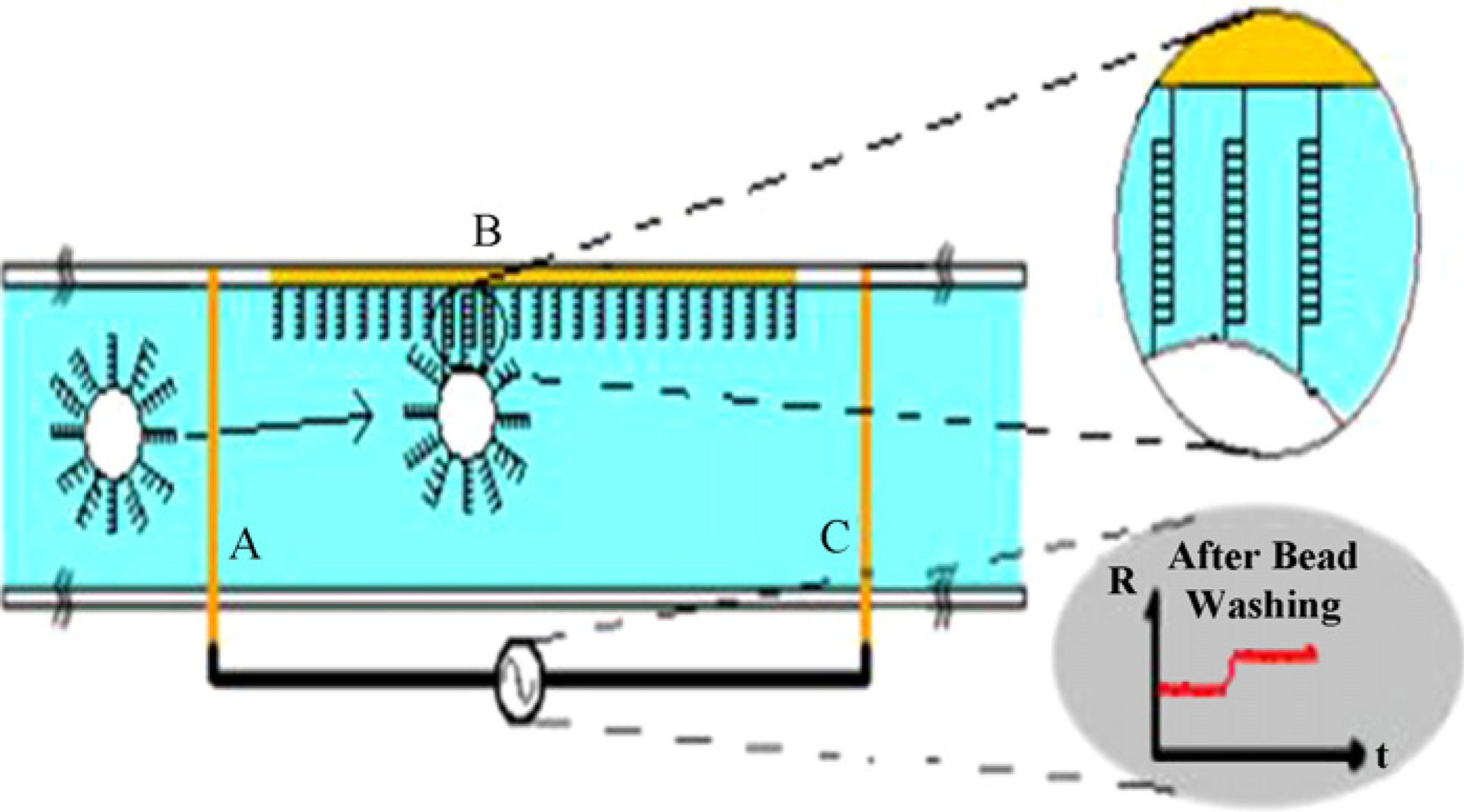
In the microchannel gating technique for DNA biomarker detection, DNA probe moleculesare immobilized on the surface of the microchannel. Target DNA molecules areimmobilized on the surface of micron sized beads. The beads are then injected into themicrochannel (Fig. 1A) partially clogging the channel resulting in an instantaneous increasein the baseline resistance (Fig. 1C). The requirement for successful detection of the DNA
NIH-PA Author Manuscript
hybridization (Fig. 1B) is that the surfaces of the microspheres contain target DNAs whichare specific and complementary to the probe DNAs immobilized on the active area of thesensor. In order to be able to detect the hybridization resulting in the capture of a singlebead, it is also necessary that the microspheres used be comparable in size to that of thechannel geometry.
Alternatively it is possible to run this assay without immobilizing the target DNA on thebeads. In this assay, the test sample containing the target DNA, functionalized with a linkermolecule such as biotin at the 5′ end, is injected into the channel pre-functionalized withDNA probe molecules, in which the 5′ end is attached to the surface. After hybridizationoccurs, the 5′ end of the target DNA will be exposed to the solution. Thus if a bead coatedwith a molecule such as streptavidin passes through, it can bind to the biotin on the targetDNA. This format is more suitable for multiplexing since it would not be necessary toseparately functionalize each bead with a different target DNA.
2. Experimental procedures
In this section we describe the procedure required to fabricate the microsensors, and also the
NIH-PA Author Manuscript
procedure to functionalize the beads and the channel surface with the target DNA and theprobe DNA molecules respectively.
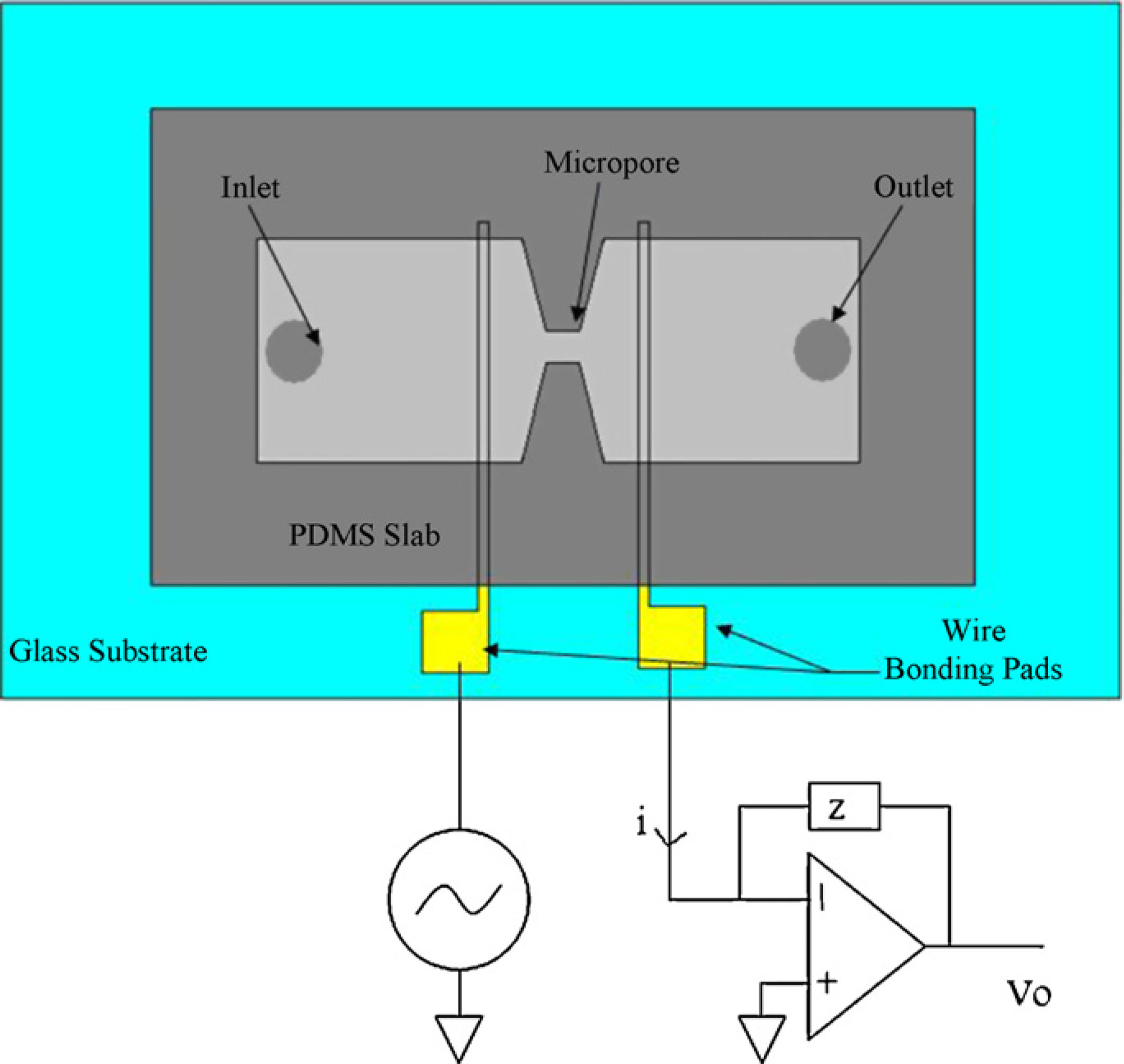
A schematic of the sensor is shown in Fig. 2. The microsensor consists of gold electrodes ona glass substrate covered with a PDMS slab embedded with a microfluidic channel. Au/Crelectrodes (with a thickness of 200 nm/15 nm) were patterned using evaporation and thenlift-off and were then cut into separate pieces. The electrodes were 10 µm in width. Au/Crelectrodes were micropatterned on a glass wafer using traditional photolithography,sputtering, and then lift-off processing and then cut into separate chips using a wafer saw.
The microchannels were fabricated in PDMS. The master mold for the microchannels waspatterned onto a silicon substrate using SU-8 photoresist (fabricated by the Stanford Microfluidics Foundry). PDMS (10:1 prepolymer:curing agent) was poured onto the master moldand allowed to cure for 2 h at 80 °C. Holes of 1 mm in size were punched through the pdms
Sens Actuators B Chem. Author manuscript; available in PMC 2013 March 25.
Javanmard and Davis
to make inlets and outlets of the channels. The glass chips and the PDMS slabs were alignedand then bonded together after oxygen plasma treatment.
NIH-PA Author Manuscript
Tygon tubing was attached to the inlet and was connected to a 50 µl syringe, where the flowwas controlled by a syringe pump (Harvard Appartaus Model 11, Instech Solomon,Plymouth Meeting, PA).
2.2. Measurement apparatus
Electrical impedance measurements were collected across the channel in the region betweenelectrodes A and C. We applied a voltage signal to electrode A and a low noise currentpreamplifier (Stanford Research Systems Model SR570) to electrode C in order to measurethe current across the channel and then the data was collected with a National Instrumentsdata acquisition card and read by a Labview program. The channels were also monitoredusing optical microscopy in order to confirm that the electrical signal changes were due tobeads binding in between the electrodes.
Given that we want to detect the presence of the microspheres due to the resulting change inchannel resistance, we want to minimize the effect on the impedance measurement resultingfrom all impedances except for the bulk solution resistance. This can be achieved byworking at sufficiently high frequencies, where from our previous work we measured to be
NIH-PA Author Manuscript
20 kHz. For our channel and electrode geometry, 30 kHz was an optimum frequency fordevice operation. At frequencies below this, the impedance due to the double layercapacitance had not yet completely diminished, however as the frequency of the excitationvoltage signal was increased above 30 kHz, the output signal became noisier.
In this assay the target DNA consisted of the following sequence, 5′-AGGT GTGG GGTGA TCA TTTG TCAG TGTG AGGG AGTG TGGT AGTG C-3′, and the probe DNAconsisted of 5′-ACAC CTGC ACTA CCAC ACTC CCTC ACAC TGAC AAAT GATCACCCC-3′. The target DNA sequence, of 45 base pairs, was biotinilated at the 5′ end.
2.3. Channel surface chemistry
The probe DNA sequence was biotinilated at the 5′ end. Biotinilated Bovine SerumAlbumin was immobilized on the bottom of the surface channel by physical adsorption.
Afterwards, Streptavidin was incubated in the channel for 15 min in order to bind onto thebiotinilated BSA. The biotinilated probe DNA was then incubated in the channel to becaptured by the streptavidin molecules. Incubation times of at least 15 min were necessary toproduce optimal immobilization results. The channel surface was then blocked using 1 mg/ml of Bovine Serum Albumin (BSA).
NIH-PA Author Manuscript
2.4. Bead washing
Fifty microliters of solution (PBS buffer) containing 0.5% (m/v) 20 µm polystyrene beadsprecoated with streptavidin (Spherotech Inc., Lake Forest, IL) was prepared. The solutionwas rotated for 15 min in order to prevent precipitant from forming. The solution was thencentrifuged, the supernatant removed, and the beads were again re-suspended in PBS. ThePBS buffer had a salt concentration of 700 mM NaCl which is required for rapidhybridization of DNA strands. This process was repeated three times in order to ensure thatall free target DNA strands were removed from the solution. The same procedure was alsoused to coat 10 µm polystyrene beads precoated with streptavidin (Spherotech Inc., LakeForest, IL) with DNA.
Sens Actuators B Chem. Author manuscript; available in PMC 2013 March 25.
Javanmard and Davis
3. DNA quantification assay
In order to characterize the ability of our sensor to quantify target DNA and to determine the
NIH-PA Author Manuscript
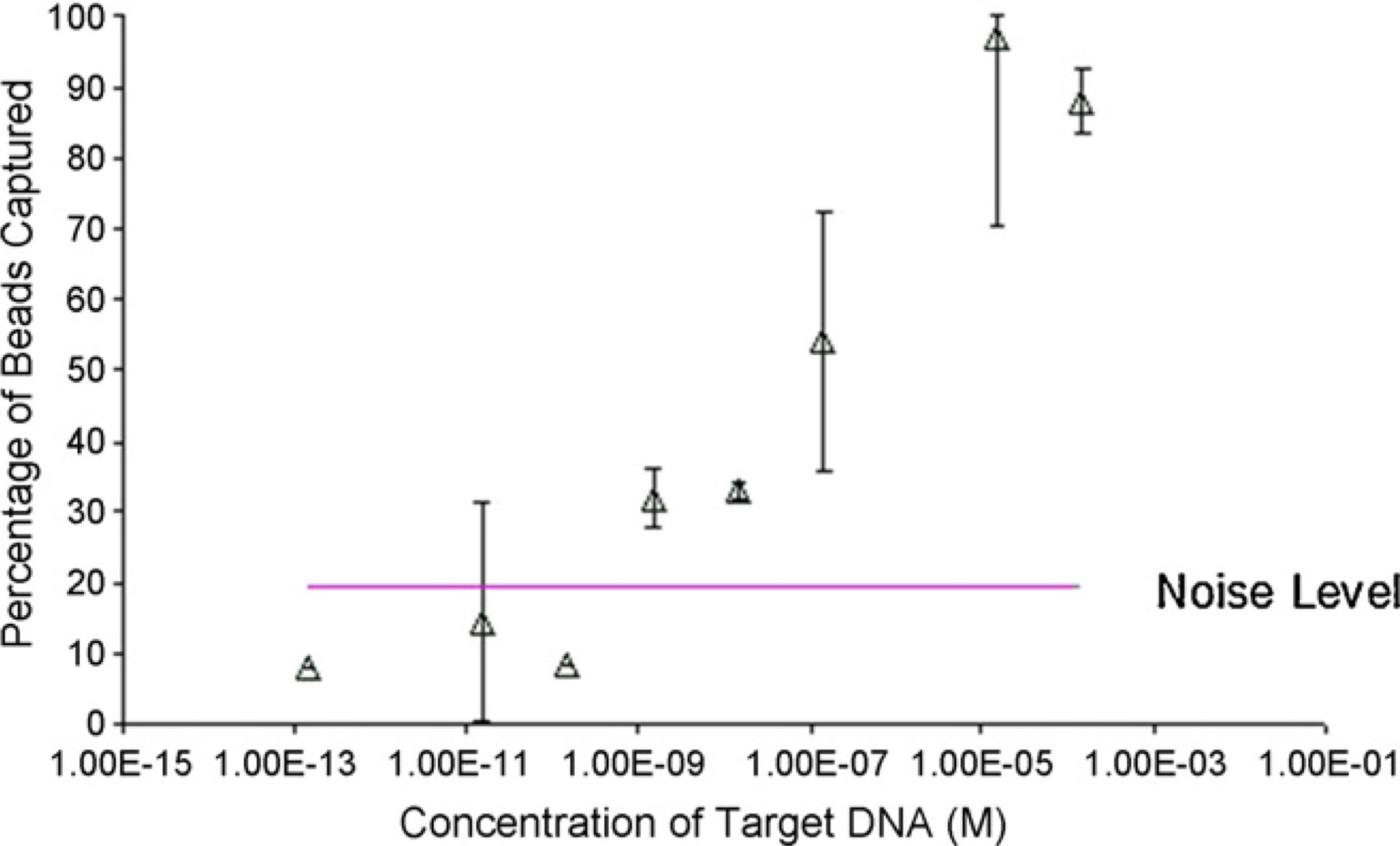
detection limit we optically examined the percentage of beads captured in the microchannelas a result of DNA hybridization. For this assay we used a 200 µm wide 50 µm deepchannel. The test sample, which contained the target DNA, was injected and incubated for30 min in the channels which were immobilized with probe oligonucleotides, allowing forenough time for the target DNA to hybridize to the probes. Afterwards, the 10 µm beadswhich are precoated with streptavidin are injected into the channel until the surface iscompletely covered with beads. The beads are incubated in the channel for 1 min, which wassufficient time to allow them to come to rest so that the streptavidin on the bead can bind tothe biotin on the 5′ end of the target DNA which should be facing upward. A flow of 90 nl/min was applied to the channel which provided enough shear force to pull off the beadswhich had not bound to the surface of the channel, while those which the streptavidin andbiotin were bound together remained intact. We performed this assay for variousconcentrations of target DNA suspended in PBS buffer. The NaCl concentration of the PBSbuffer was increased to 800 mM, which is necessary for the hybridization reaction to occurin a timely manner. The channels were monitored under an optical microscope. The numberof beads both before and after the application of the flow was counted manually (by eye)and the results are plotted in Fig. 3 along with the standard error bars. The beads all tend to
NIH-PA Author Manuscript
settle to the bottom of the channel, so it is clear for one who looks under the microscope thatthe beads that are counted both before and after application of flow are only a monolayer. Asthe concentration of the target DNA increases, the number of beads attached increases untilit reaches saturation at 10 µM. When no target DNA is present in the test sample, themaximum percentage of beads ever binding was 20% however, the average was around fivepercent.
4. Minimizing false positive signals
It is important to minimize the false positive signals which arise from beads nonspecificallybinding to the surface of the channel. This result can be due to electrostatic interactionsbetween the beads and the channel surface, the nonspecific interactions between the DNAand the surface, beads coming to rest on the surface, and many other causes. In general beadcapture due to DNA strands hybridizing is higher in affinity compared to nonspecificallybound beads. By adjusting the flow rate such that the drag force on the beads is strongenough such that nonspecifically bound beads can be pulled off while the beads bound dueto DNA hybridization remain attached; it is possible to minimize the nonspecificinteractions.
NIH-PA Author Manuscript
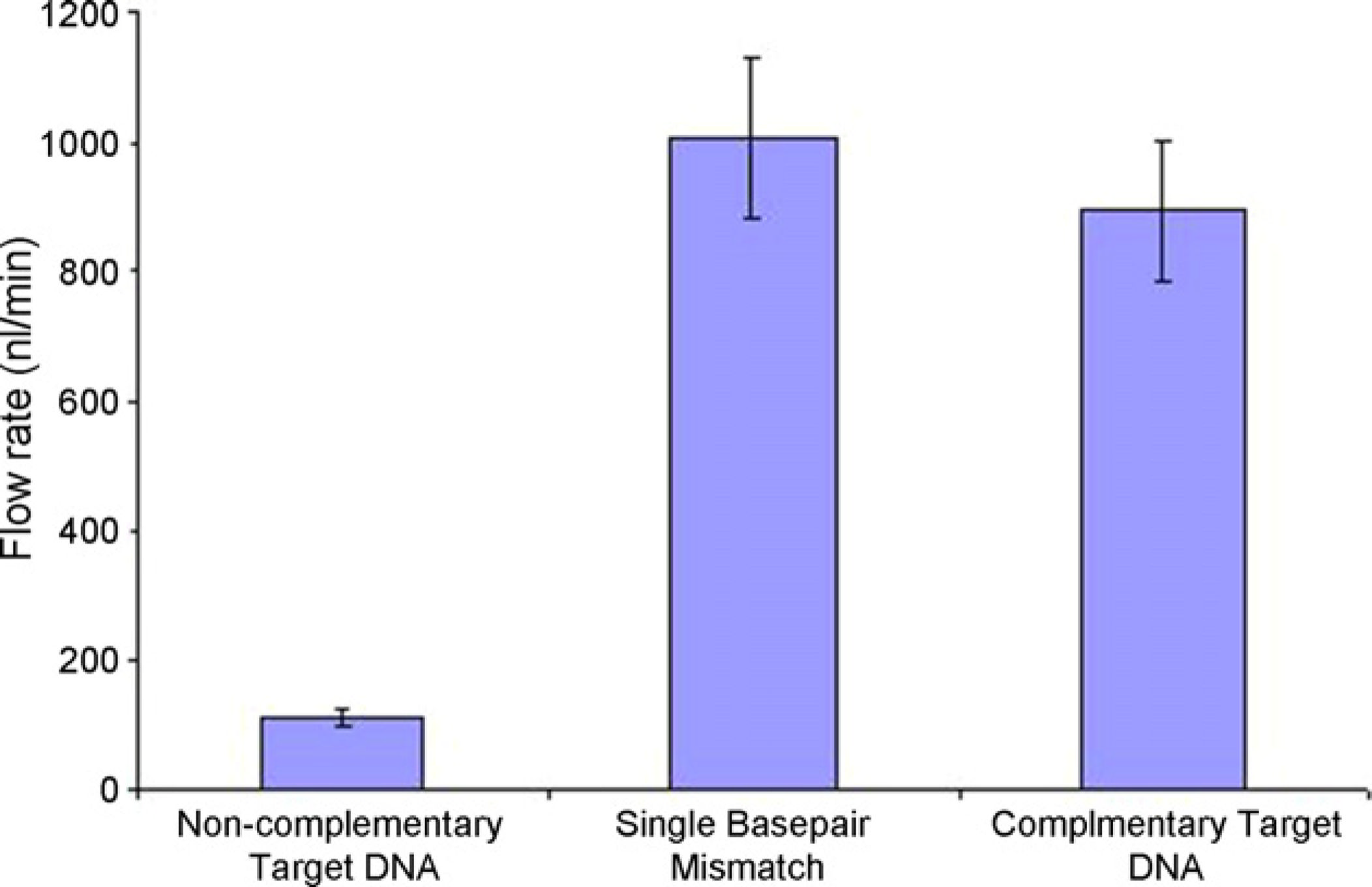
In this assay the target DNA consisted of the following sequence, Biotin-5′-AGGTGTGGGGTGATCATTTGTCAGTGTGAGGGAGTGTGGTAGTGC-3′, and theprobe DNA consisted of Biotin-5′-ACAC CTGC ACTA CCAC ACTC CCTC ACACTGAC AAAT GATC ACCCC-3′. We also examined a target DNA strand with a singlebase pair mismatch in the 27th position of the sequence. In this assay we used 10 µm beads.
The beads for each assay were separately incubated in the channel for 1 min. The flow ratewas incrementally increased as the beads were pulled off. The average flow rates and thestandard error required to detach the beads from the surface of the channel are shown in Fig.
4. In the first column the target DNA on the beads and the probe DNA on the channelsurface were non-complementary with each other, and were not expected to hybridize. Aflow rate of 100 nl/min was required to wash off the beads. In the second column, the targetDNA and the probe DNA were mismatched by a single base pair, requiring a high flow rateof 1000 nl/min to wash off the beads. In the third column the target DNA and the probe
Sens Actuators B Chem. Author manuscript; available in PMC 2013 March 25.
Javanmard and Davis
DNA were complementary to each other also requiring a high flow rate of 900 nl/min towash off the beads. In the second case, the single base pair mismatched DNA unexpectedly
NIH-PA Author Manuscript
has a higher affinity compared to the perfectly matched DNA, however their error bars overlap with each other. With more experiments, it is expected that these two average flow rateswill converge. With lengths of DNA as long as those we have examined in this study, we areunable to distinguish between single base pair mismatches and perfectly complementaryDNA. This may however be more feasible with shorter length DNA molecules. We willexplore these issues in future studies.
One of the advantages of this technique lies in the fact that by operating at the optimal flowrate the nonspecifically bound beads will not get a chance to become permanently attachedto the channel surface, while the specifically bound beads will get captured and remainattached. A flow rate window between 70 and 350 nl/min will minimize the false positivesignals.
DNA microarrays typically require overnight incubation before the hybridization can bedetected. Using our biochip we are able to achieve detection of hybridization within a halfhour. Given that in DNA microarrays tens of thousands of different probe DNA moleculesare being tested against a mixed soup of DNA molecules, it is expected that the overallhybridization time will be much larger than the case which we tested. However, a half hour
NIH-PA Author Manuscript
is still more rapid than that which can be achieved with fluorescent detection, which is onthe order of several hours. The reason for this great decrease in analysis time is a result ofthe number of molecules required to hybridize before being detectable by the sensingapparatus. For fluorescent detection technologies, at least several thousand molecules arerequired to hybridize before producing enough optical signal to be detected by thefluorescent scanners. In the case of our assay, this number can be determined by calculatingthe affinity of the beads to the surface of the microchannel, and then determining the numberof hybridized DNA molecules by dividing the total force by the force holding a singlemolecule together.
5. Calculation of the affinity of the beads and the channel surface
The flow rate in the channel is directly proportional to the drag force applied to the beads.
The drag force required to detach the beads from the surface of the channel is equal to thebinding force between the hybridized DNA molecules. In order to determine the bindingforce between the hybridized DNA molecules accurately using the flow rates in Fig. 4, itwould be necessary to perform a rigorous calculation of the relationship between the flowrate and the drag force on a sphere on the bottom of a microchannel with the dimensions ofour fabricated channels. However, in order to get a quick order of magnitude estimate of the
NIH-PA Author Manuscript
drag force, it is possible to use the sphere-drag formula of Stokes [9]:
where U is the mean velocity at which the sphere travels, and a is the radius of the sphere.
An average flow rate of roughly 900 nl/min was required to pull the beads off the surface ofthe channel which corresponds to a drag force of 126 pN. The rupture forces for largermolecules of DNA tends to saturate at around 70pN [4]. This means that on average thebeads are held attached to the base of the channel by the force of one or two DNAmolecules. Given that the biotin streptavidin bond is in general much stronger than that oftwo hybridized DNA strands, we assume that the two complementary DNA strands arebeing pulled apart before the biotin streptavidin interaction breaks.
Sens Actuators B Chem. Author manuscript; available in PMC 2013 March 25.
Javanmard and Davis
This confirms our initial hypothesis regarding the reason for the rapid hybridizationdetection rates. This is due to the fact that a single DNA molecule hybridizing is sufficient to
NIH-PA Author Manuscript
cause the bead to get captured, compared to fluourescent detection technologies whichrequire several thousand DNA molecules to hybridize in order to generate enough opticalsignal to be detectable by the fluorescent scanners.
6. DNA real-time assay
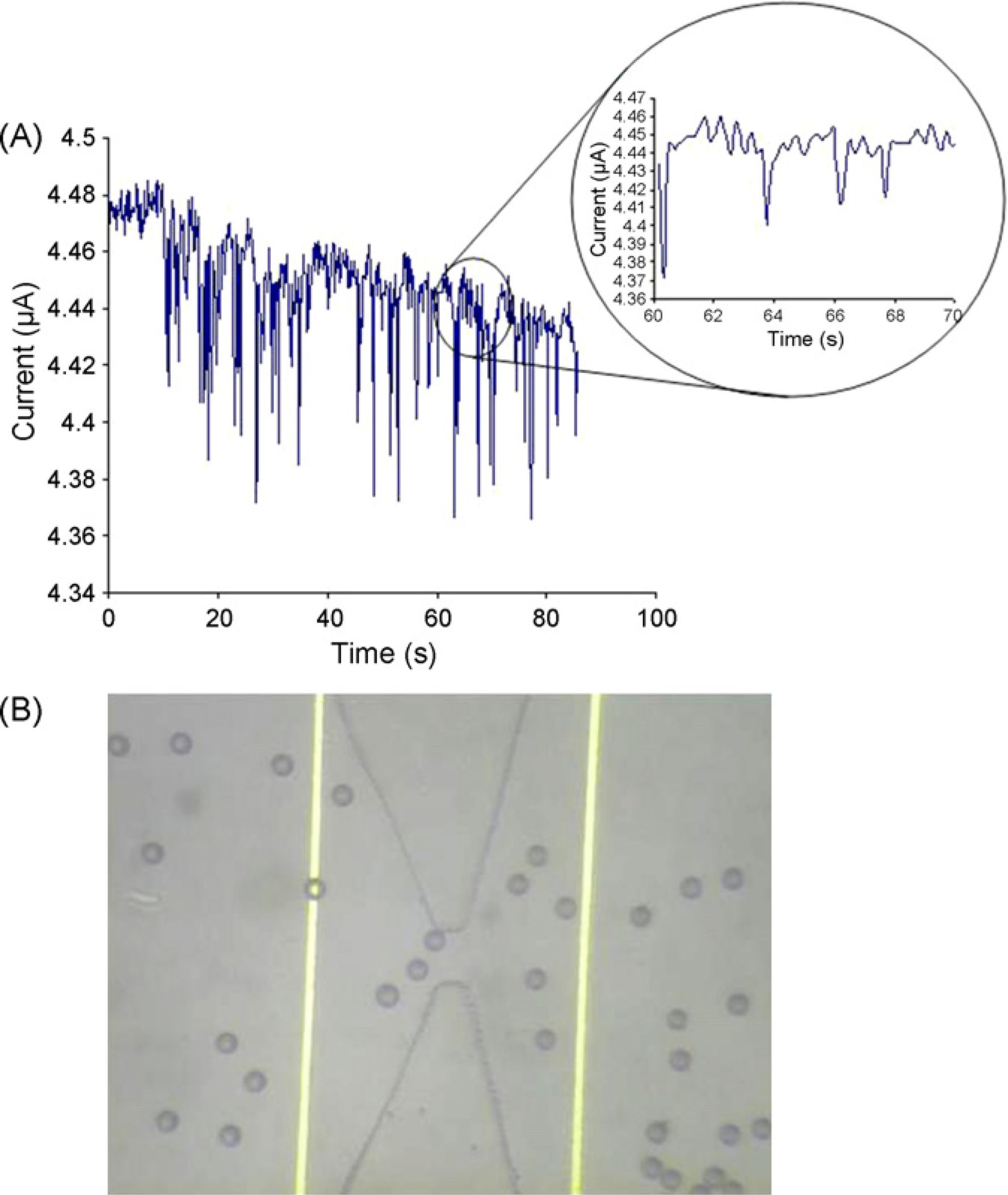
The 20 µm beads coated with streptavidin were injected into the non-activated microchannelat a flow rate of 175 nl/min. Here we have used a two electrode configuration, where twoelectrodes surround the pore. We measure the impedance across the pore at a frequency highenough such that the impedance contribution from the parasitic double layer capacitance isminimized, and the impedance is dominated by the bulk resistance across the pore. We havefound this optimum frequency to be 30 kHz as described in our previous work [7]. Weperform this measurement by tying the left electrode to a 30 kHz waveform generator, andthe right electrode to a current preamplifier, and from this the current passing through thepore is obtained. The current was monitored across the micro-pore as shown in Fig. 5(A).
An optical micrograph showing the beads passing through the channel is shown in Fig. 5(B).
The downward spikes correspond to beads passing through the channel. The reason for thevariance in the pulse heights is due to the fact that the drop in current is proportional to the
NIH-PA Author Manuscript
location of the bead relative the central axis as it passes through the pore. Multiple beadspassing across the pore will also result in a larger current drop. The widths of the pulses area function of the time of flight across the pore.
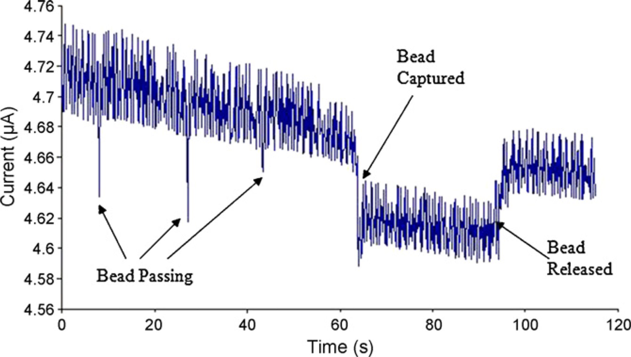
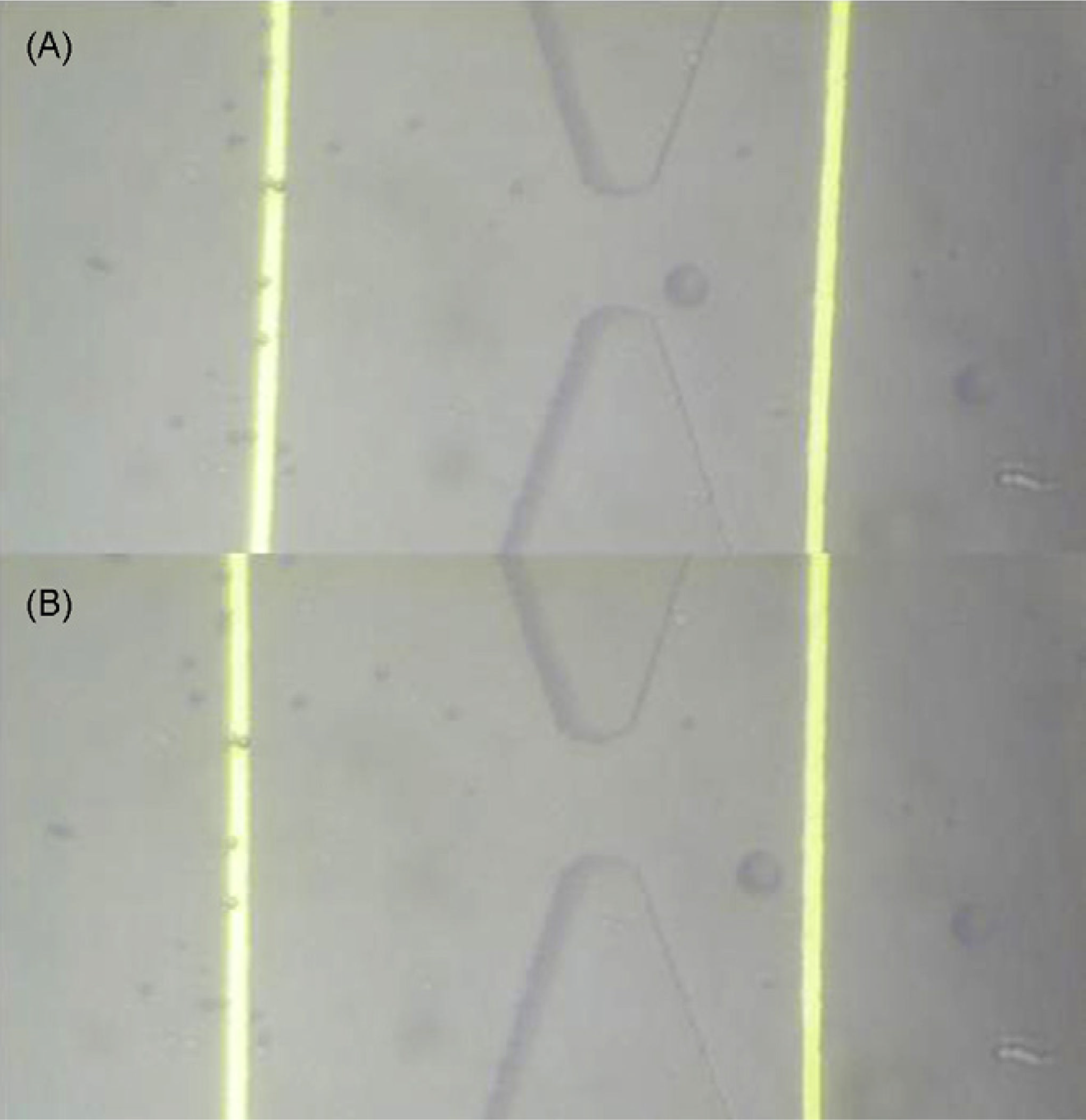
In Fig. 6, we show representative data of a positive experiment where hybridized DNA isattached to the surface and the biotin is exposed to the channel so that the streptavidincoated beads can get captured at the surface. The sharp downward peaks in the current resultin beads passing through the pore. At roughly t = 65 s, as a bead is captured beside the pore,a permanent drop in the current results until roughly t = 95 s where the bead again detachesand exits the pore. In Fig. 7(A), an image is shown of a bead in the vicinity of the pore,which is close enough (to the pore) to cause a steady state current drop as seen in Fig. 6. Fig.
7(B) shows an image of the bead exiting the pore.
In this paper we have demonstrated the ability of our biochip to detect the hybridization ofcomplementary DNA molecules within a half hour. Our system is advantageous overconventional fluorescent detection technologies because the readout time is reduced by atleast an order of magnitude without the need for any fluorescent labels. The costs required
NIH-PA Author Manuscript
for labelling on a generic fluorescent DNA chip average at roughly $20, whereas the use ofpolystyrene microspheres for labelling averages at about $3 per chip, a decrease of one orderof magnitude. A sample volume of roughly 0.1 µl is required to perform this assay. Theability to detect DNA hybridization on chip electrically opens up the potential formultiplexed detection of nucleic acid biomarkers on a portable device which can be a goodcandidate for use in the clinical setting. Although, this type of system will not be able tocompete with DNA microarrays, which can achieve multiplexed detection of hundreds ofthousands of genes, our platform is useful in the clinical setting where one would need aportable platform to inexpensively analyze less than 100 genes for biomarker detection.
We would like to express our appreciation to the Stanford Microfluidics Foundry for their help in fabricating ourmicrofluidic channels in PDMS. This work was supported by National Institutes of Health Grant P01 HG000205.
Sens Actuators B Chem. Author manuscript; available in PMC 2013 March 25.
Javanmard and Davis
1. Brown PO, Botstein D. Exploring the new world of the genome with DNA microarrays. Nat. Genet.
NIH-PA Author Manuscript
1999; 21:33–37. [PubMed: 9915498]
2. Mackay IM. Real-time PCR in the microbiology laboratory. Clin. Microbiol. Infect. 2004; 10(3):
190–212. [PubMed: 15008940]
3. Ayliffe HE, Frazier AB, Rabbitt RD. Electric impedance spectroscopy using microchannels with
integrated metal electrodes. J. Microelectromech. Syst. 1999; 8(1):50–57.Carbonaro A, Sohn LL. Aresistive-pulse sensor chip for multianalyte immunoassays. Lab Chip. 2005; 5(10):1155–1160.
[PubMed: 16175273] Gawad S, Schild L, Renaud P. Micromachined impedance spectroscopy flowcytometer for cell analysis and particle sizing. Lab Chip. 2001; 1(1):76–82. [PubMed: 15100895]Gomez R, Bashir R, Sarikaya A, et al. Microfluidic biochip for impedance spectroscopy ofbiological species. Biomed. Microdev. 2001; 3(3):201–209.Liu YS, Walter TM, Chang WJ, et al.
Electrical detection of germination of viable model Bacillus anthracis spores in microfluidicbiochips. Lab Chip. 2007; 7(5):603–610. [PubMed: 17476379] Mingqiang Y, Ki-Hun J, Lee LP.
Theoretical and experimental study towards a nanogap dielectric biosensor. Biosens. Bioelectron.
2005; 20(7):1320–1326. [PubMed: 15590285] Radke SM, Alocilja EC. Design and fabrication of amicroimpedance biosensor for bacterial detection. IEEE Sens. J. 2004; 4(4):434–440.Radke SM,Alocilja EC. A microfabricated biosensor for detecting foodborne bioterrorism agents. IEEE Sens.
J. 2005; 5(4):744–750.Zheng G, Patolsky F, Cui Y, et al. Multiplexed electrical detection of cancermarkers with nanowire sensor arrays. Nat. Biotechnol. 2005; 23(10):1294–1301. [PubMed:16170313]
NIH-PA Author Manuscript
4. Yin F, Guo M, Yao S. Kinetics of DNA binding with chloroquine phosphate using capacitive
sensing method. Biosens. Bioelectron. 2003; 19(4):297–304. [PubMed: 14615086]
5. Javanmard M, Talasaz AAH, Nemat-Gorgani M, et al. Targeted cell detection based on
microchannel gating. Biomicrofluidics. 2007; 1(4):044103–044101.
6. Javanmard M, Talasaz AH, Nemat-Gorgani M, et al. A microfluidic platform for characterization of
protein–protein interactions. Sens. J. IEEE. 2009; 9(8):883–891.
7. Javanmard M, Talasaz AH, Nemat-Gorgani M, et al. lectrical detection of protein biomarkers using
bioactivated microfluidic channels. Lab Chip. 2009; 9(10):1429–1434. [PubMed: 19417910]
8. Zhong JF, Chen Y, Marcus JS, et al. A microfluidic processor for gene expression profiling of
singlehumanembryonic stem cells. Lab Chip. 2008; 8(1):68–74. [PubMed: 18094763] Yoanna C,Mikkel N, Susanne P, et al. Multiplex SNP genotyping using locked nucleic acid and microfluidics.
2001; 6(4):92–97.Eszter S, András G. Genotyping with microfluidic devices. Electrophoresis. 2006;27(24):4896–4903. [PubMed: 17117382]
9. White, FM. Viscous Fluid Flow. 2nd ed. Boston, Massachusetts: McGraw-Hill; 1991.
Mehdi Javanmard received his BS degree with highest honors from the Georgia Institute
NIH-PA Author Manuscript
of Technology in 2002, and the MS degree from Stanford University in 2004, and the PhDdegree from Stanford University in 2008 all in Electrical Engineering. He has held researchpositions in Georgia Tech Research Institute, Lawrence Livermore National Laboratory,Stanford Linear Accelerator Center, and Stanford Genome Technology Center. His mainresearch areas are biosensors, biolectronics, and microfluidics with an emphasis on detectionof pathogenic bacteria, genetic biomarkers, and protein biomarkers. He is currently anEngineering Research Associate at Stanford University.
Ronald W. Davis received the BS degree in Mathematics, Physics, Chemistry, and Botany
from East Illionois University in 1964, and the PhD in Chemistry from California Institute
of Technology in 1970. He is considered to be a world leader in biotechnology, and the
development and application of recombinant DNA and genomic methodology to biological
systems. His laboratory has developed many of the techniques currently used in academic
and industrial biotechnology laboratories. He is also considered to be a world expert in the
Sens Actuators B Chem. Author manuscript; available in PMC 2013 March 25.
Javanmard and Davis
electron microscopy of nucleic acids and has developed many of the mapping methods forwhich he received the Eli Lilly Award in Microbiology in 1976. His laboratory was also
NIH-PA Author Manuscript
instrumental in the development of lambda vectors, which were commonly used for theprimary cloning of DNA molecules in E. coli. His laboratory also developed many of theyeast vectors and helped to develop yeast as a host for recombinant DNA for which hereceived the United States Steel Award in 1981, presented by the National Academy ofSciences. In 1983 he became a member of The National Academy of Sciences. He was a co-author on a publication that first described a new approach for conducting human geneticsand for the construction of a human genetic linkage map for which he received the RosentielAward for Work in Basic Medical Research. His laboratory is now conducting genomicanalysis of Saccharomyces cerevisiae for which he received the 2004 Lifetime AchievementAward from the Yeast Genetics Society. His laboratory is developing many newtechnologies for the genetic, genomic, and molecular analysis of model organisms andhuman with a focus on clinical medicine for which he received the 2004 Sober Award fromthe American Society for Biochemistry and Molecular Biology (ASBMB/IUBMB).
NIH-PA Author Manuscript
NIH-PA Author Manuscript
Sens Actuators B Chem. Author manuscript; available in PMC 2013 March 25.
Javanmard and Davis
NIH-PA Author Manuscript
NIH-PA Author Manuscript
Fig. 1.
(A) Surface of the microchannel is activated with oligonucleotide probes. Target DNA
strands are immobilized on the surface of polystyrene beads, which are injected into the
microchannel. (B) Hybridization of the DNA strands causes capture of beads resulting in (C)
an increase in the channel resistance. Alternatively, if the target DNA can be functionalized
with a biotin molecule, the test sample can be injected into the channel and incubated. After
the hybridization is compelted, streptavidin coated beads can be injected into the channel to
bind onto the biotinilated target DNA.
NIH-PA Author Manuscript
Sens Actuators B Chem. Author manuscript; available in PMC 2013 March 25.
Javanmard and Davis
NIH-PA Author Manuscript
NIH-PA Author Manuscript
NIH-PA Author Manuscript
Fig. 2.
Schematic of the microfluidic biosensor and the setup used for measuring the current across
the pore. A function generator is tied to the left electrode, and a current preamplifier to the
right electrode for converting the current to a voltage.
Sens Actuators B Chem. Author manuscript; available in PMC 2013 March 25.
Javanmard and Davis
NIH-PA Author Manuscript
NIH-PA Author Manuscript
Fig. 3.
Optical results for DNA quantification. As target DNA concentration increases, the
percentage of the beads which remain attached also increases, and our detection limit is
about 1 nM.
NIH-PA Author Manuscript
Sens Actuators B Chem. Author manuscript; available in PMC 2013 March 25.
Javanmard and Davis
NIH-PA Author Manuscript
NIH-PA Author Manuscript
Fig. 4.
The average flow rate required to pull off all of the beads attached to the base of the channel,
and also the standard error bars. In the first column, the target DNA and the probe DNA
were completely mismatched, thus a negligible flow rate was sufficient to pull off the beads.
In the second column, the DNA on the beads was mismatched with the probe DNA on the
channel surface by a single base pair, and a flow rate of 1000 nl/min was necessary to pull
off the beads. In the third column, where the target and probe DNA were expected to
hybridize a flow rate greater than 900 nl/min was required to pull the beads off. In order to
minimize the false positive signals due to beads nonspecifically binding, one must operate
within the flow rate window between 100 and 900 nl/min.
NIH-PA Author Manuscript
Sens Actuators B Chem. Author manuscript; available in PMC 2013 March 25.
Javanmard and Davis
NIH-PA Author Manuscript
NIH-PA Author Manuscript
NIH-PA Author Manuscript
Fig. 5.
(A) Control experiment. Current across the pore being monitored as beads pass through the
pore in a control experiment with no probe DNA immobilized on the surface. The
downward spikes seen after t = 10 s are due to beads passing through the pore. (Inset) A
closeup of the data between t = 60 s and t = 70 s. (B) Optical image of 20 µm beads passing
through the pore.
Sens Actuators B Chem. Author manuscript; available in PMC 2013 March 25.
Javanmard and Davis
NIH-PA Author Manuscript
NIH-PA Author Manuscript
Fig. 6.
Current across the pore being monitored in a functionalized channel. The downward peaks
correspond to beads passing through the channel. At time t = 60 s, the sharp drop
corresponds to a bead getting capture, which is why the current does not rise up again
instantaneously. At t = 90 s the bead becomes detached from the channel surface rising up
again near it's original level.
NIH-PA Author Manuscript
Sens Actuators B Chem. Author manuscript; available in PMC 2013 March 25.
Javanmard and Davis
NIH-PA Author Manuscript
NIH-PA Author Manuscript
NIH-PA Author Manuscript
Fig. 7.
Image of a single bead situated in the pore. A single 20 µm bead trapped in this vicinity of
the pore will cause the permanent current drop similar to that seen in Fig. 6. (B) Image of
bead released and exiting the pore.
Sens Actuators B Chem. Author manuscript; available in PMC 2013 March 25.
Source: http://www.lorentzcenter.nl/lc/web/2013/576/KeyGene/A%20microfluidic%20platform%20for%20electrical%20detection%20of%20DNA%20hybridization_nihms206460.pdf
A Technology Review on Virtual Colonoscopy Virtual Colonoscopy: An Alternative Approach to Examination of the Entire Colon Jerome Z. Liang Departments of Radiology, Computer Science and Biomedical Engineering State University of New York, Stony Brook, NY 11794, USA We have developed a virtual colonoscopy system aiming toward mass screening for polyps through the entire colon. This work reviews the key technical components of the system. Introduction Colorectal carcinoma is the second leading cause of cancer-related deaths among men and women in the United States, following lung cancer, with 56,000 deaths reported in 1998 and an estimated over 130,000 new cases per year [21]. Unfortunately the symptoms of colon cancer, such as anemia and change in bowel habits, are neither sensitive nor specific. Diagnosed cancers are often in the later stage of development, resulting in a high mortality incidence. Most colon cancer probably arises from polyps, which can take 5 to 15 years for malignant transformation. Recent studies have shown that screening of colonic polyps can reduce the mortality rate from the cancer. Optical colonoscopy and barium enema are the two most commonly used diagnostic procedures. Other tools include fecal occult blood testing (which detects only 30-40% of colorectal cancer and 10% of adenomas) and sigmoidoscopy (which fails to detect lesions in the proximal colon, where 40% of all cancers occurs, and misses 10-15% sigmoid colon carcinomas [5, 10, 15, 37]). While optical colonoscopy is accurate and can biopsy detected polyps, it is expensive ($1,800), invasive (requires scope insertion), uncomfortable (colon washing and sedation required), time consuming (hours), and carries a small risk of perforation and death (colonic perforation in one in 500 to 1000 cases and death in one in 2,000 to 5,000 cases [29]). It fails to demonstrate the entire colon in 10-15% of the cases and thus misses 10-20% of the lesions [10, 15]. Barium enema is less expensive ($400) and non-invasive, but it is less accurate (less than 78% sensitivity in detecting polyps of size from 5 to 20 mm diameter [28]), more time consuming, and requires a good deal of patient positioning and cooperation when X-ray radiographs of the colon are taken at various views. An accurate, cost-effective, non-invasive, comfortable procedure for mass screening of colonic polyps with a size less than 1 cm in diameter is extremely valuable, since the detection and removal of these small polyps will totally cure the patient. Since 1994, several pilot studies [16, 19, 23, 31, 34, 39] evaluating the feasibility of virtual colonoscopy as an alternative means for colon screening have motivated a great amount of research interests ranging from image formation, and segmentation, to visualization [1, 3, 10, 11, 13, 20, 22, 26, 27, 32, 33, 38]. This alternative means utilizes computer virtual-reality techniques to navigate inside the reconstructed three-dimensional (3D) colon model created from computed tomography (CT) or magnetic resonance (MR) images, looking for polyps. It starts with a bowel cleansing procedure, similar to that used in conventional optical colonoscopy, and is followed by inflating the colon with room air or CO2 gas --- if CT modality is utilized --- introduced through a rectal insert.
A Note from Americans for Safe Access We are committed to ensuring safe, legal availability of marijuana formedical uses. This brochure is intended to help doctors, patients andpolicymakers better understand how marijuana—or "cannabis" as it ismore properly called—may be used as a treatment for people with seri-ous medical conditions. This booklet contains information about usingcannabis as medicine. In it you'll find information on:


