
Cialis ist bekannt für seine lange Wirkdauer von bis zu 36 Stunden. Dadurch unterscheidet es sich deutlich von Viagra. Viele Schweizer vergleichen daher Preise und schauen nach Angeboten unter dem Begriff cialis generika schweiz, da Generika erschwinglicher sind.
Bemo-modellbahn.de
ANSPRUCHSVOLLE SCHWEIZER UND DEUTSCHE
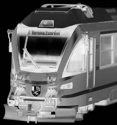
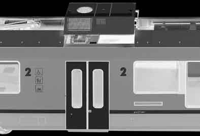
RhB ABe 8/12 3501-3515
Bedienungsanleitung • Operating Instructions • Instructions de service
Bedienungsanleitung • Operating Instructions • Instructions de service
Al gemeine Hinweise
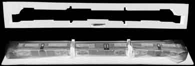
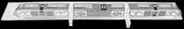
Komplette Verpackung (ohne Stülpdeckel) mit dem weißen
Schachtelunterteil nach oben auf die dünne Schaumstoffa-
bdeckung ablegen. Durch leichtes Spreizen im Bereich des
Mittelwagens läßt sich die weiße Schachtel und danach ge-
nauso die Schaumstoffhül e abnehmen. Dann die Distanz-
stücke zwischen den Wagen nach unten herausziehen und
den Zug mit beiden Händen aufstel en. Bitte vergessen Sie
nicht, diese Transportsicherung beim Verpacken des Zuges
wieder zwischen den Wagen einzusetzen.
Bedingt durch die komplexe Ausführung der 2+8-poligen
Verbindung zwischen den Fahrzeugen auf beengtem Bau-
raum ist ein Einsatz auf einem Gegenbogen Radius 330 mm
nur mit einer zwischengeschalteten Gerade von mindestens
56,5 mm (entsprechend Gleis 4282 000) möglich. Grund-
sätzlich empfehlen wir für einen reibungslosen Betrieb die
Verwendung größerer Radien und eben verlegter Gleise.
Übertriebene Gleisüberhöhungen und Unebenheiten kön-
nen von Fahrwerk und Kupplung nur bedingt ausgeglichen
werden und zum Entgleisen führen. Das vorliegende Modell für das Zweileiter-Gleichstromsy-
stem (12 V) wird durch einen 5-poligen Gleichstrommotor
mit Schwungmasse (Art. 1244 000 330) angetrieben.
Zum Schutz der Elektronik ist es wichtig, daß die Fahrt-
richtung des Zuges nur bei Stillstand und nicht bei Fahrt
After removing the lid of box turn the box upside down
Il faut retirer vers le haut l‘embal age en entier (sans le cou-
onto a flat surface so that the soft foam top sheet is bet-
vercle du dessus) avec la partie inférieure blanche et dépo-
ween the work surface and the train. Remove the white
ser le tout sur la fine feuil e de mousse. Après une légère
box (which is now on the top) by pul ing the long sides
pression dans la région de la voiture centrale, il est possible
open from the middle and then remove the outer foam
de retirer l‘embal age blanc et ensuite d‘enlever la mousse.
packaging. Final y remove the foam spacers from between
Retirer ensuite les pièces entre les voitures en les tirant pru-
the coaches. Without bending the units pick up with both
demment vers le bas. La rame sera alors redressée et dépo-
hands and place the model on the track. Please remember
sée à deux mains sur la voie. N‘oubliez pas de remettre les
to install the shipping locks again when putting the model
protections en cas de rembal age de la rame.
back into the box.
A cause de la complexité de construction du connecteur
Due to the complex design of the 2+8 pin electrical cou-
à 2+8 pôles et du peu de place entre les véhicules, il faut
pling in the tight space between the cars, the train set can
en cas de courbe suivie d‘une contre courbe de rayon de
only negotiate s-curves with a 330 mm radius that feature an
330 mm intercaler un élément droit de minimum 56,5 mm
intermediate straight track section with a minimum length
(morceau droit 4282 000). Nous vous recommandons pour
of 56.5 mm (such as track 4282 000). For smooth operation
une exploitation sans problème d‘utiliser des rayons plus
we recommend using curves with a large radius and level
grands et un placement correct de la voie. Des inégalités et
track. Banked rail or uneven track can only be compensa-
des crocs dans la voie trop importants sont difficilement ac-
ted to a certain extend by the couplers and the bogies and
ceptables par la motorisation et les attelages, ils conduisent
hence may cause derailments.
à un dérail ement.
This train set for 12V DC operation is powered by a 5 pole
Le modèle est conçu pour le système 2 rails courant conti-
motor with flywheel (part number 1244 000 330).
nu (12 V), il est entraîné par un moteur à courant continu 5
Do not change the direction of travel while the train set
pôles avec volant d‘inertie (Art. 1244 000 330).
is in motion as this can damage the electronic circuits of
Afin de protéger l‘électronique, il est important
the model!
d‘effectuer le changement de sens de marche unique-
ment lorsque la rame est à l‘arrêt complet. Le non-respect
de cette consigne peut détruire les diodes.
Bedienungsanleitung • Operating Instructions • Instructions de service
Bedienungsanleitung • Operating Instructions • Instructions de service
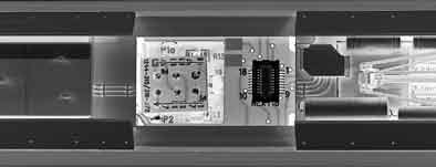
Die Stromaufnahme erfolgt werkseitig im Analogbetrieb
über den führenden Endwagen sowie das diesem zuge-
wandte Drehgestell des angetriebenen Mittelwagens.
Hier steckt in der Motorleiterplatte der mit vier Dioden be-
stückte 6-polige Brückenstecker. Soll der Mittelwagen nicht
zur Stromaufnahme herangezogen werden, sind die grauen
oder schwarzen Kabel von den Radschleifern an den Kon-
takten P1a, P2, P3a und P4 von der Motorleiterplatte abzulö-
ten und zu isolieren. Im Digitalbetrieb muß der mit zwei aufgelöteten Drähten
bestückte Brückenstecker in die Motorleiterplatte gesteckt
werden. Damit werden al e sechs Drehgestel e des Zuges
zur Stromaufnahme herangezogen. Fal s nur eine Zughälfte
zur Stromaufnahme dienen sol , kann der eingelötete Draht
entsprechend der Zeichnung aufgetrennt werden.
Ein Austausch der beiden sechspoligen Stecker zur Steu-
erung der Stromaufnahme erfolgt nach Abheben des Kli-
maanlagenaufsatzes auf dem Dach des Mittelwagens. Dazu
muß auch der Analogstecker Next18 entfernt werden. Für einen einwandfreien Kontakt sol ten die Schienen re-
gelmäßig z.B. mit einem Schienenreinigungsgummi oder
-wagen gesäubert werden. Der Zug ist umspurbar für H0e-
Current col ection
When the factory setup is for analogue operation, the cur-
rent is col ected by the bogies of the respective end car and
the bogie of the motor car that is closest to the end car. In
this case the motor circuit board (PCB) is equipped with a 6
pole strapping connector featuring four diodes. To disable
current col ection via the bogies of the motor car, discon-
nect and insulate the grey or black wires from the wheel
contacts at contacts P1a, P2, P3a and P4 on the PCB.
For digital operation, the strapping connector that features
two wires soldered onto it, needs to be plugged into the
motor circuit board. In this case all six bogies are used for
current col ection. To disable current col ection by the rear
bogies disconnect the wires as shown.
Remove the air-conditioning unit on the roof and the Next18
connector to replace the 6 pole strapping connector.
An uninterrupted current col ection can be achieved by
4 frequently cleaning the rails with a suitable rubber or track
cleaning wagon. The train set can be re-gauged for H0e
La prise de courant en exploitation analogique se fait
d‘origine par les deux extrémités de la rame ainsi que par le
bogie moteur de la voiture centrale. Dans cel e-ci se trouve
la platine comprenant le connecteur de pontage à 6 pôles
et 4 diodes. Au cas où la prise de courant centrale n‘est pas
utilisée, il faut dessouder de la platine et isoler les fils gris ou
noirs des contacts P1a, P2, P3a et P4. En exploitation par système numérique il faut enficher le
connecteur de pontage avec deux fils gris dans la platine
du moteur. Les six bogies prise de courant sont alors utilisés.
En cas de prise de courant par seulement une demi-rame
(utile en analogique pour les sections d‘arrêt courtes), le fil
correspondant sera déconnecté.
L‘accès aux deux connecteurs qui servent pour l‘alimentation
est possible en soulevant l‘imitation de la climatisation sur le
toit de la voiture médiane. Il faut aussi enlever le connecteur
analogique Next18. Pour assurer un bon roulement, il faut régulièrement net-
toyer les rails avec une gomme de nettoyage ou un wagon
nettoyeur. La rame peut être modifiée pour la circulation sur
des voies H0e.
Bedienungsanleitung • Operating Instructions • Instructions de service
Bedienungsanleitung • Operating Instructions • Instructions de service
Digitalbetrieb und Sound
Das Modell des „Al egra" ist mit einer Schnittstel e Next18
ausgerüstet. Diese befindet sich unter dem abnehmbaren
Klimaanlagenaufsatz auf dem Dach des Mittelwagens. Für
Digitalbetrieb den Analogstecker entnehmen und gegen
einen Decoder/Sounddecoder Next18 ersetzen. Bitte
beachten Sie unbedingt, daß in der im Mittelwagen darun-
terliegenden Motorleiterplatte der sechspolige Brücken-
stecker mit den beiden aufgelöteten Drähten eingesetzt ist
(siehe Kapitel Stromaufnahme)!
Im Digitalbetrieb mit einem Next18-Decoder sind die fahrt-
richtungsabhängige LED-Stirnbeleuchtung 3+1 weiß sowie
die Innenbeleuchtung unabhängig voneinander schaltbar.
Die Beleuchtung des Führerstandes ist elektrisch an das
obere Spitzenlicht gekoppelt.
Beide Endwagen sind zur Aufnahme je eines Lautsprechers
mit Durchmesser 23 mm vorbereitet. Dazu den einge-
klipsten inneren, an den Lautsprecherbohrungen erkenn-
baren Kasten auf der Unterseite der Endwagen abnehmen
und das Bal astgewicht gegen einen geeigneten Lautspre-
cher tauschen. In der Lautsprecheraufnahme finden Sie je
zwei Kabel zum Anlöten der Lautsprecher.
Bitte achten Sie bei der Wahl der Lautsprecher unbedingt
auf die Spezifikationen des Sounddecoders!
Digital operation and sound
The „Alegra" train set is equipped with a Next18 interface.
It is situated below the removable air-conditioning unit on
the roof of the motor car. For digital operation, remove the
analogue connector and insert a decoder/sound decoder
Utilisation en numérique et avec bruitage (Sound)
Next18. Make sure that the motor circuit board is equipped
Le modèle de la rame ALLEGRA est pourvu d‘une interface
with the 6 pole strapping connector that features two
Next18. El e se trouve sous l‘imitation de la climatisation
wires (refer to section current col ection above). In digital
sur le toit de la voiture centrale. Pour le fonctionnement en
operation the selective LED head light 3+1 and the interior
système numérique il faut retirer le connecteur analogique
lighting can be switched on and off independently. The
et le remplacer par un décodeur ou un décodeur „sound"
lighting of the driver‘s cab is linked with the top head light.
Next18. Vérifier aussi impérativement sur la platine dans la
Both end cars can be fitted with a speaker of 23 mm
voiture médiane que le connecteur de pontage avec les
diameter. This can be done by removing the underfloor
deux fils soudés est bien enfoncé (voir chapitre sur la pri-
equipment box featuring a speaker gril e and replacing the
se de courant). En système numérique avec un décodeur
bal ast with a suitable speaker. The speaker support is fitted
Next18, il est possible de commander séparément les LED
with two wires that can be soldered to the speaker. Make
blanches des phares avant qui fonctionnent selon le sens
sure the speaker matches the specification of the sound
de marche en 3+1. L‘éclairage intérieur est aussi commandé
séparément, l‘éclairage du poste de conduite est relié au feu
supérieur avant.
Un emplacement pour un haut-parleur (HP) de 23 mm de
diamètre est prévu dans chaque voiture d‘extrémité. Il faut,
pour accéder à ces emplacements, retirer en dessous de la
rame les gril es de protection et retirer du logement la pièce
métal ique servant de bal ast pour y placer le HP. Dans le
logement il y a deux fils à souder aux HP. Faites attention aux
spécifications du décodeur lors du choix des HP.
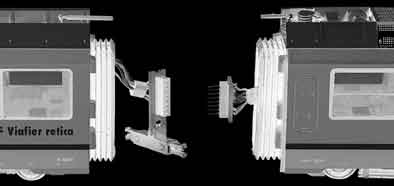
Trennen der Zugeinheit und Abnehmen
Das Trennen der dreiteiligen Zugeinheit erfolgt - sofern
überhaupt notwendig - durch vorsichtiges horizontales
Auseinanderziehen von End- und Mittelwagen auf einer
ebenen Unterlage. Zur Vermeidung von Schäden an der
elektrischen Steckerverbindung bitte die Fahrzeuge nicht
zu weit auseinanderziehen und keinesfal s eines der Fahr-
zeuge schräg nach oben bewegen! Zuerst wird nacheinan-
der die zweipolige Kupplung zur Stromübertragung aus der
Kupplungskulisse beider Fahrzeuge ausgeklipst. Danach
kann man die achtpolige Steckerverbindung trennen. Beim
Zusammenkuppeln zuerst die Kupplungen am Mittelwa-
gen montieren, den Stecker verbinden und dann die Ver-
bindungsstange mit Sorgfalt in die Kulisse der Endwagen
Separation of the train set and removal of the car bodies
Séparation des voitures et dépose des carrosseries
Only separate the train set when real y required. Careful y
La séparation des voitures de tête et de la voiture centrale
pull the front and motor car apart horizontal y on a level
doit se faire uniquement en cas de nécessité absolue avec
surface. The electrical connection is easily damaged if the
beaucoup de précautions et sur une surface bien plane. Afin
cars are pul ed apart too far. Do not cant any car or slant it
de ne pas endommager les connecteurs électriques entre
upwards. Remove the two pole connection from the coup-
les différents éléments, il ne faut pas écarter les voitures
ler and then disconnect the eight pole connector.
trop loin les unes des autres. Il ne faut en aucun cas soulever
To recompose the train set start with mounting the coup-
les voitures de biais avant d‘avoir déconnecté les liaisons as-
lers at the motor car. Then connect the 8 pole connector
surant le passage du courant. Déclipser ensuite les liaisons
before careful y inserting the coupler into the shaft of the
mécaniques de chaque côté de la voiture centrale, ensuite
le connecteur à 8 pôles peut être retiré. Pour reconstituer
l‘ensemble de la rame, il faut d‘abord remonter sur la voiture
centrale les connecteurs électriques des deux côtés, ensuite
encliqueter avec prudence les pièces mécaniques de liaison
dans les coulisses d‘attelage.
Bedienungsanleitung • Operating Instructions • Instructions de service
Bedienungsanleitung • Operating Instructions • Instructions de service
Das Mittelwagengehäuse wird durch drei Schrauben auf
der Unterseite des angetriebenen Wagens befestigt. Nach
dem Lösen der Schrauben den Wagenkasten nach oben
abheben und dabei die Kupplungskulisse leicht nach in-
nen drücken. Die Steckkupplungen dürfen hierbei natürlich
nicht mehr eingesteckt sein. Obwohl das Getriebe werkseitig mit Spezialfett geschmiert
ist, empfehlen wir nach längerer Betriebsdauer oder bei
lauter werdendem Fahrgeräusch die Motorwel enlager mit
einem kleinen Tröpfchen Model bahnöl und das Schne-
ckengetriebe sowie die Achslager mit Molykote-Getriebe-
fett (verdünnt mit Model bahnöl) zu schmieren.
The car body of the motor car is fixed by three screws on
the lower side of the undercarriage. Unscrew and lift the
car body while slightly pressing the shaft for the coupler in-
wards. Ensure that the coupler is removed from the shaft.
The gear mechanism comes greased with a special lubri-
cant. After a long running time or when the gear noise in-
creases we recommend greasing the motor shaft bearings
with a small drop of model railway lubricant. The worm gear
and the wheelset bearing should be greased using Molyko-
te gear oil diluted with model railway lubricant.
La carrosserie de la voiture centrale est maintenue par trois
vis en dessous de cel e-ci. Après retrait des vis, il faut sou-
lever la carrosserie vers le haut et en même temps pousser
légèrement les coulisses d‘attelage vers l‘intérieur. Les con-
necteurs ne doivent naturel ement pas être en place.
Malgré que le modèle soit graissé d‘origine, nous vous con-
seil ons après un certain temps d‘utilisation, ou en cas de
fonctionnement bruyant, de lubrifier avec de l‘huile pour
modèles réduits le cardan du moteur ainsi la transmission
par ressort hélicoïdal ainsi que les boîtes d‘essieux avec de
la graisse Molycote (al ongée d‘un peu d‘huile).
Die Endwagen weisen Klipsverbindungen zwischen Wa-
genboden und Fensterstreifen auf. Zuerst müssen die ein-
gesteckten äußeren Bahnräumer vorsichtig nach vorne ab-
genommen werden. Das Abheben des Wagenkasten erfolgt
durch leichtes Spreizen des Wagenkastens - am Einfachsten
zuerst vorne abheben und danach den hintenen Teil mit
Kulisse und Kabelbaum durch die Faltenbalgöffnung durch-
führen. Bitte achten Sie wegen der Kabelverbindungen da-
rauf, auch die Inneneinrichtung mit herauszunehmen. Beim
Zusammenbau zuerst hinten einsetzen und dabei auf die
Kupplungsleiterplatte und die Kabel achten.
The end cars feature snap joints between floor and window
line. First, remove the front snow plough by careful y pul ing
it forward. The car body can be removed by slightly strut-
ting apart the side wal s. Lift the front of the car body first
and then pull the undercarriage including the coupler shaft
and the harness out of the folding bel ow. Due to the wires
present it is important that the interior is removed together
with the undercarriage. To reassemble the end car, insert
the coupler shaft into the folding bel ow first and pay atten-
tion to the coupler with the 8 pole connector.
Les voitures d‘extrémité sont munies de liaisons par clips
entre le sol et les fenêtres. Il faut avant tout retirer prudem-
ment vers l‘avant les socs chasse-neige. Le soulèvement de
la carrosserie se fera plus facilement en écartant et en sou-
levant d‘abord le côté avant, ensuite la partie arrière avec
les câbles en la guidant à travers l‘ouverture du soufflet.
Attention de soulever aussi l‘aménagement intérieur vu les
câbles qui s‘y trouvent. Lors du remontage remettre d‘abord
la partie arrière en faisant bien attention aux liaisons de la
platine ainsi qu‘aux câbles.
Bedienungsanleitung • Operating Instructions • Instructions de service
Bedienungsanleitung • Operating Instructions • Instructions de service
Zum Umbau auf Oberleitungsbetrieb müssen al e drei Wa-
gen geöffnet werden. Bei den Endwagen wird das graue
oder schwarze Kabel von der Kupplungskulisse auf ei-
ner Seite am Kontaktband abgelötet und mit dem an der
Inneneinrichtungsleiterplatte angelöteten grauen bzw.
schwarzen Oberleitungskabel gemäß Zeichnung mit einem
Verlängerungskabel verbunden (Verbindungsstel en isolie-
ren!). Sofern beide Schienen am Gleis kurzgeschlossen sind
empfehlen wir, beide Kontaktbänder durch eine Kabelbrü-
cke zu verbinden. Bitte beachten Sie, daß am zweiten Mit-
telwagen die richtige Seite modifiziert wird.
Beim Mittelwagen werden die an der Motorplatine angelö-
teten grauen bzw. schwarzen Kabel von P4 nach P3a bzw.
von P2 nach P1a umgelötet. Nach Abschluß dieser Arbeiten
sind die beiden Stromabnehmer auf den Steuerwagen ent-
sprechend einem Vorbildeinsatz auf der Berninabahn ein-
satzfähig. Soll auch der Stromabnehmer auf dem Mittelwagen
(Stammnetzbetrieb) aktivieriert werden, muß zusätzlich
noch eine weitere Kabelverbindung gemäß Zeichnung ge-
lötet werden.
Overhead line operation
To modify the train set for overhead line operation it is re-
quired to remove all three car bodies as described above.
Both end cars need to be modified as fol ows: unsolder the
grey or black wire originating at the coupler on the strip
conductor of the printed circuit board. Use an extension
wire to connect the unsoldered end with the grey or black
cable from the current col ector that is soldered to the cir-
cuit board as shown. Make sure to insulate the connections.
If both rails are short-circuited on your display we recom-
mend connecting the two strip connectors with a jumper
cable as shown. It is important that the correct side is modi-
fied at both end cars as shown. Modify the motor car as fol ows: The grey or black wires sol-
dered to the motor circuit board are unsoldered at contact
P4 and soldered to P3a and unsoldered at contact P2 and
soldered to P1a respectively. Now the current col ectors of
the end cars are both operational as required for authentic
Bernina line operation. To activate the current col ector of
10 the motor car for authentic main line operation an additi-
onal connection needs to be soldered to the circuit board
located below the air-conditioning unit as shown.
Fonctionnement par caténaire
Pour assurer le fonctionnement par caténaire, les trois voi-
tures doivent être ouvertes. Dans les voitures d‘extrémités
il faut dessouder les fils gris ou noirs venant de la coulisse
de l‘attelage vers la piste du circuit imprimé, et souder ces
fils en les prolongeant sur la platine selon le dessin. Il faut
bien isoler la jonction de cette prolongation. Les deux rails
de la voie étant alors court-circuité, nous recommandons
de relier les deux pistes par un câble de pontage. Veil ez à
respecter et à modifier le bon côté sur la voiture centrale
(Risque de court-circuit avec les deux voitures de tête).
Les fils gris ou noirs doivent être déplacés dans la voiture
centrale de P4 vers P3a et de P2 vers P1. Après cette modifi-
cation, les deux pantographes sur les voitures de tête sont
en service et prennent le courant comme dans la réalité sur
la ligne de la Bernina. Si le pantographe de la voiture cen-
trale doit être connecté (comme sur le réseau principal), il
faut encore souder un fil supplémentaire comme indiqué
sur le dessin.
Bedienungsanleitung • Operating Instructions • Instructions de service
Bedienungsanleitung • Operating Instructions • Instructions de service
Bedienungsanleitung • Operating Instructions • Instructions de service
Bedienungsanleitung • Operating Instructions • Instructions de service
Im beiliegenden Zurüstbeutel finden Sie einige Ansetzteile
zur Verfeinerung des Model zuges, die entweder nur einge-
steckt oder mit Kunststoff- bzw. Sekundenkleber fixiert wer-
den müssen. Die Rückspiegel sind in verschiedenen Winkeln
(angelegt oder ausgefahren) montierbar. Dazu die dickere
Hülse oben am Ansetzteil in der Aufnahme vermitteln.
Der zweite Satz Bahnräumer, Hülse und Mittelpuffer sind
verfügbar sofern keine Kupplung am Endwagen benötigt
wird. Dazu die Kupplung und Abdeckplatte abklipsen. Ein
Kurzkupplungsadapter ist derzeit nicht verfügbar.
Im Zurüstbeutel befindet sich beim Analogmodell die in
den Kapiteln Stromaufnahme und Digitalbetrieb beschrie-
bene eine 6-polige Austauschleiterplatte zur Steuerung der
Stromaufnahme.
Zudem enthalten sich verschiedene zwischen den Wagen
einzusetzende hochflexible Verbindungsschläuche. Diese
werden in die entsprechenden Kappen an den Wagenstirn-
wänden eingepreßt und sind primär für Vitrinenmodel e
The trainset can be fitted with detailing parts that are ship-
ped separately. These are simply inserted or fixed with pla-
stic adhesive or super glue. The rear view mirrors can be
mounted in a retracted or deployed state. This is done by
inserting the mirror shaft into the support as required.
The couplers of the end cars can be replaced by authentic
center buffers using the extra set of snow ploughs provided.
A close coupling adaptor is currently unavailable.
Models for analogue operation come with a replacement
circuit board for digital operation as described in the sec-
tion „digital operation and sound". For static models, flexi-
ble jumper cables and hoses can be mounted to connect
the car bodies by inserting them into the connection boxes
Pièces de détail age
Dans le sachet inclus dans le modèle vous trouverez plu-
sieurs pièces de détail age pour affiner le modèle réduit.
Certaines sont simplement enfichées, d‘autres doivent être
col ées avec de la col e pour matière plastique ou avec de
la col e instantanée. Les rétroviseurs peuvent être montés
avec différents angles (fermé ou ouvert). Il faut pour cela
utiliser le bossage en haut de la carrosserie.
Le deuxième jeu de chasse-neige, de bossage et de tampon
central sont utilisable à condition qu‘il n‘y ait pas d‘attelage
aux voitures d‘extrémités. Il faut pour cela déclipser
l‘attelage et le cache. Il n‘y a pas pour le moment d‘attelage
court disponible.
Le sachet de pièces comprend un connecteur à six pôles de
rechange pour configurer la prise de courant, ainsi que des
imitations très flexibles de tuyaux pneumatiques se trou-
vant entre les véhicules. Ceux-ci doivent être enfoncés dans
les logements prévus entre les voitures, ils sont principale-
ment conçus pour l‘exposition du modèle en vitrine.
Bedienungsanleitung • Operating Instructions • Instructions de service
nderungen vG ÄO K. C
odeleisenbahnen GO MEM B
BEMO Model eisenbahnen GmbH u. Co. KG
Postfach 1234 • D-73063 Uhingen
Source: http://www.bemo-modellbahn.de/fileadmin/bemo/files/produktblaetter/7244_000_903.pdf
A SURVEY OF TIME-OF-USE (TOU) PRICING AND DEMAND-RESPONSE (DR) PROGRAMS July 2006 Submitted By: Energy & Environmental Economics 353 Sacramento Street, Suite 1700 San Francisco, CA 94111 (415) 391-5100 The U.S. Energy Environmental Protection Agency (U.S. EPA) commissioned this report to support state public utility commissions in their expanding use of energy efficiency (EE) in their states. The report is part of the EPA-State Energy Efficiency and Renewable Energy (EERE) Project index.htm). The EPA-State EERE Projects are a joint initiative between the U.S. EPA, the National Association of Regulatory Utility Commissioners, and individual state utility commissions designed to explore approaches that deliver significant energy cost savings and other benefits through greater use of energy efficiency, renewable energy, and clean distributed generation.
Experimental treatments for spinal cord injury: What you should know (Version 2) A guide for people living with spinal cord injury, their family, friends and health care professionals John D Steevesa, James W Fawcettb, Mark H Tuszynskic, Daniel P Lammertsed, Armin Curte, Michael G Fehlingsf, James D Guestg, Naomi Kleitmanh, Andrew R Blighti, Douglas J Brownj, Michael Haakk, Harvinder S Chhabral, Hideyuki Okanom, Li Jianjun. a.


