Doi:10.1016/j.nimb.2005.03.243

Nuclear Instruments and Methods in Physics Research B 236 (2005) 11–20 High energy ion beam irradiation of polymers for electronic applications D. Fink a,*, P.S. Alegaonkar a,b, A.V. Petrov a,c, M. Wilhelm a, P. Szimkowiak a, M. Behar d, D. Sinha a,e, W.R. Fahrner f, K. Hoppe g, L.T. Chadderton h a Hahn-Meitner-Institut, Glienicker Str. 100, D-14109 Berlin, Germany b Department of Physics, University of Pune, Pune 411 007, India c Inst. of Solid State Physics, NASB, P.Brovka Str. 17, 220072 Minsk, Belarus d Instituto de Fı´sica, UFRGS, Campus do Vale, Porto Alegre, RG, Brazil e Department of Chemistry, Nagaland University, Lumai Campus, Nagaland 798 601, India f Chair of Electronic Devices, University of Hagen, D-58084 Hagen, Germany g South Westfalia University of Applied Sciences, D-58095 Hagen, Germany h Institute of Advanced Studies, Australian National University, Canberra, Australia Available online 19 May 2005 Ion irradiation of polymers offers a number of interesting possibilities for applications. In the case of latent tracks, radiochemical changes, phase transitions, alterations of the intrinsic free volume, or radiation induced defects can beexploited – the latter ones to trap mobile impurities. These approaches are useful to form, e.g. new types of sensors.
Apart from this, etched tracks in polymers offer a vast range of possibilities. Practically any material – including colloides and nanocrystals – can be inserted into these pores to form nanowires or nanotubules. Sequential depositioncan be made as well in radial as axial direction to form complex nanostructures. Combination with lithography enablesone to form different types of novel transistors, microcapacitors, -magnets, -transformers and -sensors. Also sterilizingfoils for medicine and packing industry have been made in this way. A number of new ideas are presented how to pro-ceed further in this field.
Ó 2005 Published by Elsevier B.V.
Keywords: Latent ion tracks; Etched ion tracks; Polymers; Applications; Electronics The recent years have brought a renaissance of Corresponding author. Tel.: +49 30 8062 3029; fax: +49 30 interest in ion tracks in polymers, for the sake of E-mail address: (D. Fink).
novel applications. One has to distinguish between 0168-583X/$ - see front matter Ó 2005 Published by Elsevier B.V.
doi:10.1016/j.nimb.2005.03.243 D. Fink et al. / Nucl. Instr. and Meth. in Phys. Res. B 236 (2005) 11–20 the application of latent, i.e. as-implanted ion unsaturations, double bonds, and (4) phase trans- tracks, and etched tracks. The primary deposition formations, such as amorphisation. These changes of high energy (MeV to GeV) inside a tiny are responsible for the four major strategies that target volume (Ôion track coreÕ, 10 15. . 14 cm3), have emerged for latent track applications: (1) and within an extremely short time (10 17. . 15 s), exploitation of the modified transport properties by swift heavy ions leads to dramatic transient along ion tracks, (2) trapping of mobile (e.g.
modifications of the materials via chemical and metallic) atoms, molecules or clusters along the structural changes (e.g. the transient breaking of tracks, (3) exploitation of the materialÕs chemical all bonds), with accompanying heat and pressure changes, and (4) making use of ion-induced phase pulses. In spite of repair of much of the primary damage during the annealing phase after the ion The first concept is exploited in using swift impact (Ôthermal spikeÕ, 10 12. . 11 s), quite a heavy ion irradiated polymer foils as seals to pro- number of irreversible changes remain. The cylin- tect sensitive volumes against penetration of ambi- drical zones with altered properties where these ent dust and moisture while maintaining pressure changes prevail are the so-called ‘‘latent tracks''.
equilibrium and gas exchange with the ambient.
Dissolution of the latent track material by suitable It can also be realized, together with the second agents (ÔetchingÕ) leads to the formation of pores, concept, by the decoration of latent tracks by liq- the so-called ‘‘etched tracks''. By careful selection uids and solutes dissolved in them , by grafting of projectile, target, etchant, and etching condi- specific monomers onto the host polymer along tions, the etched track can be tailored towards the ion track or by trapping of metal atoms any required shape, such as cylindrical, conical, along the tracks that will thereafter cluster to form or hyperbolic, transmittent (in thin foils) or non- conducting nanowires. It has also been found that metallic nanoclusters in metal/polymer composites In a recent paper there have been outlined can be aligned along the tracks towards pearls-on- the newly emerging possibilities, and the strategies a-string-like patterns .
were summarized that had been initiated at that The third concept has been realized already time. Only a few applications that are based on manyfold, e.g. by producing dangling bonds along latent tracks have emerged since then. For contrast, the tracks that enable protonic transport for etched tracks in polymers appear to have a much hydrogen sensing purpose by the radiochemi- greater application potential. Compact rods and cal destruction of sensitive polymers such as tubules as well as dispersed nanosized matter can polysilanes that form SiC rods , or by be embedded within the etched tracks, to form organometals that form precipitates of metals or the base of various applications. Though the num- metal oxides, sulfides etc., along the tracks upon ber of present applications is still quite limited, it ion irradiation. The emerging anisotropy of the appears that ion tracks in polymer foils will soon conductivity of such irradiated materials can find a multitude of new interesting applications be used to create novel electronic structures (the not only in electronics but also in other fields such so-called TEAMS (= tunable electronic aniso- as medicine or optics. Some of them are summa- tropic materials on semiconductors) structures rized here, and a few examples are described in for advanced devices. The last concept, final- ly-phase transformations-hardly applies to irradi-ated polymers. Here, rather carbon allotropes areused, such as diamond , or fullerite in which 2. Applications of latent tracks conducting latent tracks are formed upon irradia-tion, by transformation of sp3 bonds towards sp2 Latent tracks in polymers are characterized by along the ion paths.
(1) structural changes such as an altered free Summarizing, most of these concepts aim at volume, carbonaceous clusters, etc., (2) a high den- producing conducting nanowires in one or the sity of radicals, (3) chemical changes such as other way. In contact with semiconducting sub- D. Fink et al. / Nucl. Instr. and Meth. in Phys. Res. B 236 (2005) 11–20 strates these nanowires form Schottky nanodiodes.
walls (). In fact, this may even be beneficial The multitude of such parallel nanodiodes, eventu- for tailoring the track resistivity an capacity to- ally interacting with each other, enables one to wards any desired value, via the choice of the construct electronic building blocks of higher com- chemical deposition time that determines the size plexity, which we denoted as TEMIPOS (tunable of the precipitating nanoclusters, and hence the electronic material with irradiated polymers on intercluster distance–consequently also the type semiconductor) structures . One could also of the electrical conduction mechanism, and its think at producing arrays of nanoscopic thermo- dependence on voltage and temperature. Apart couples by appropriate materialÕs choice for both from the possibility to tailor the electrical proper- the nanowires and substrate, for future IR sensor ties of ion tracks by the precipitation of nanoclus- chips. Most of these technological approaches ters, the latter ones also possess other peculiar are still in an embryonic state.
electronic and optical properties such as a highcharge storage capacity and fluorescence, etc.,which may lead to new yet unknown challenging 3. Preparation of etched tracks for applications ion track applications.
Another possibility to cover the track walls with Etched tracks can be filled, in principle, with nanoclusters is to introduce a colloidal solution any material, and the embedded matter can be ar- into the etched tracks. Some colloidal solutions ranged as either massive wires (also called: ‘‘fibers, are already commercially available,1 others have fibrilles'') or tubules, or it just can be dispersed dis- to be made in the lab (e.g. TiO2 or LiNbO3 continuously as small nanoparticles along the When working with such colloidal solutions one track length. The techniques how to accomplish should always take into account that one does this – such as galvanic deposition, chemical depo- not work with the nanoparticle material only, sition, pressure injection, grafting, in-situ polymeri- but that the particles are surrounded by organic zation, evaporation, etc. – have been developed in ligands for stabilization, and that commercial detail during the past decade For some colloidal solution may still contain other – partly of them, e.g. the chemical deposition techniques, unknown – additives. These materials might even- it is important to provide a sufficient areal density tually modify the nanoparticle properties in an of nucleation centers on the track walls to obtain a unpredictable way.
sufficiently dense coverage of the required mate-rial. Such nucleation centers can be producedchemically, or radiochemically by irradiation with 4. Applications of etched tracks laser beams or energetic ions. The latter approachprovides a tool to tailor the track structures axially via the ranges of the used ions (Sequential galvanic deposition of different materi- Many advanced applications of etched tracks als leads to axially structured elements, and have already been reported or at least discussed, sequential chemical deposition leads to radially such as the formation of nanosized or microsized diodes ually even light-emitting Of course, some nucleation centers are always ones tunnelling structures , field present on the track walls, which are given by effect transistors , devices to control the the intrinsic polymeric surface defects such as permselectivity of electrolytes temperature- e.g. radicals or impurity atoms, but their areal den- sensitive valves miniaturized magnetic field sity is rather low for the modern synthetic poly- mers. If, e.g. during a chemical depositionprocess, one restricts to these intrinsic nucleation 1 E.g. SiO2, offered by Baier Ltd. under the trade name centers only, one will obtain only a few dispersed ÔLevasilÕ, or colloidal gold, offered by Sigma-Aldrich, or, for (semi)conducting nanocrystals on the ion track etched tracks in the lm size, also conducting silver paste.


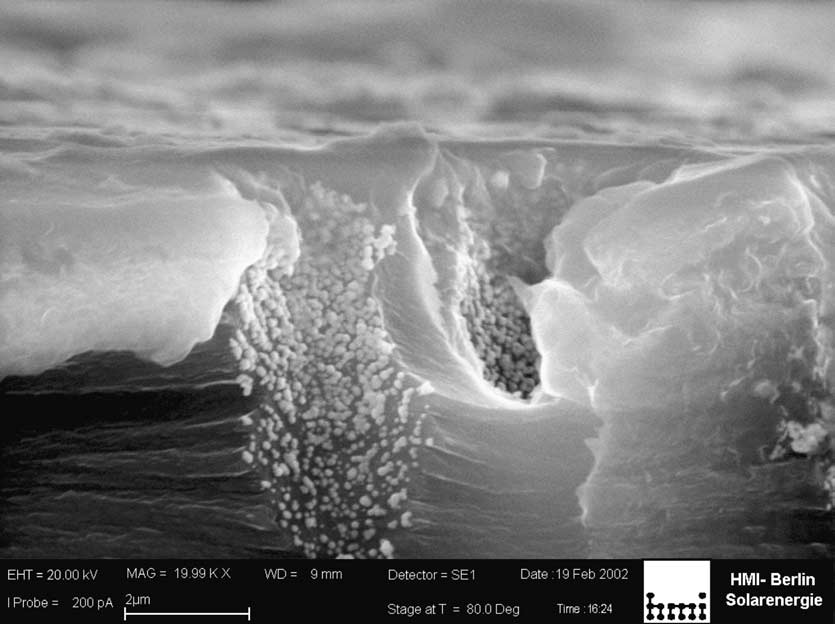
D. Fink et al. / Nucl. Instr. and Meth. in Phys. Res. B 236 (2005) 11–20 Fig. 1. Scanning microscopic view of a crack through a conical etched track in polyimide, upon which silver was chemically deposited.
As the sample had been irradiated with low energy ions (50 keV Ar+) before the silver deposition, the surface region was highlyenriched with nucleation centers, hence a continuous Ag film is deposited. On the other hand, inside the etched tracks, Ag precipitatesonly on the very few intrinsic polymeric defects.
in vivo long-time storage vessels for drugs leads to concentric nanocapacitors. Connecting miniaturized Li batteries , and sensors metallic wires embedded in etched tracks with for temperature pressure humidity suitable metal contact stripes evaporated onto and ammonia photoreceptor arrays the surface of microporous polymer foils leads to as the first stage of artificial eyes enzymatic the formation of microinductances and micro- bioreactors , preparative work for MAIA transformers .
(multianalyte immuno array) antibody chips sterilizing foils as plasters in medicine and as anti- 4.2. Ion track-based microcapacitors ageing packing materials for food and flowers,based on nanofibrilles or nanoparticles of Our first experience with nanocapacitor forma- the TiO2 phase anatase, and microwave filters tion (a)) was ambiguous. Though the ap- Some of these applications need several work- proach is, in principle, feasible, we have often ing steps such as the sequential galvanic deposition experienced local shortcuts between the two capac- of differently semiconducting (i.e. n- and p-con- itor electrodes in some tracks, so that their equiv- ducting) materials, or of metallic and semiconduct- ing wires (e.g. Cu and Se, or Ni and CdSe/CdTe) (occasionally rather small) resistance in parallel to give rise to nanometric diodes. Sequential axial with the capacitor. A much easier approach is to (e.g. galvanic) deposition of different ferromag- put a grid of opposing metal-filled ion tracks, netic materials may lead to giant magnetic reso- which are arranged like ‘‘classical'' capacitor nance (GMR) devices . Sequential radial (e.g.
plates, onto two different potentials, see chemical) deposition of different semiconductors, Such simple arrangements (showed or of metals and semiconductors leads to the a nearly constant capacity up to at least 1 GHz. In formation of concentric diodes, and the sequential fact, the replacement of the ‘‘classical'' capacitor radial deposition metal/insulator/metal structures plates (by ion track-made grids ( D. Fink et al. / Nucl. Instr. and Meth. in Phys. Res. B 236 (2005) 11–20 Fig. 2. Principle sketch of (a) an ion track-based nanocapacitor made by sequential concentrical deposition of three layers, and (b) ofan ion-track based microcapacitor, made by combination of selected (via lithography) conducting ion tracks and evaporated contacts.
(c) Image of the first microcapacitor prototype, with illustration of the capacitor function of that device. (d) Image of themicrocapacitor fine structure made of conducting tracks, with illustration of the radial electric field around such opposing tracks.
increases the capacity considerably, as can microtransformers. They showed good operation easily be derived from the corresponding well- up to 1/2 GHz, with quality factors approaching known text book formulae Polyimide is a very up to 10. These microtransformers can suffer an suitable polymer for that purpose, as its dielectric- astonishing electrical and thermal load, due to the ity coefficient is only marginally frequency depen- heat resistant carrier polymer (Kapton) used, and dent, even at the highest frequencies the rather thick copper tubules employed at thatoccasion, and (b). We have intentionally 4.3. Ion track-based micromagnets designed these magnets and transformers withmetallic tubules instead of metallic wires, in order We reported in and on the first proto- to transmit through them in future cooling gases types of ion-track based micromagnets and or liquids, to enable even higher thermal loads.
D. Fink et al. / Nucl. Instr. and Meth. in Phys. Res. B 236 (2005) 11–20 Heating of
Current / Voltage Characteristics
of ion track-based magnet
ion track-based magnet
Current [mA]
Voltage [V]
Power [ mW ]
Fig. 3. (a) Current/voltage relation of a micromagnet. The quadratic I/V correlation of that magnet ended abruptly at 1 V, when theinterface between the conducting ion track and the evaporated surface contact failed thermally. After a near-constant current atincreasing voltage, the critical contact point burnt completely at 2 V. (b) Temperature rise of a micromagnet in dependence of thedeposited power.
In fact, the first prototypes survived already some exhibits a number of specific properties which 250 mW. Failure occurred at the contact points be- make it stand in between tunable resistors, capac- tween nanotubules and evaporated contacts which itors, diodes, transistors, and sensors. It is worth hence have to be improved.
mentioning that this structure shows inherent cur- By combination of lithography with ion track rent instabilities in certain working points that technology, K. Hjort and his group succeeded make it behave similar to Esaki diodes or unijunc- meanwhile to obtain much smaller magnets with tion transistors in these cases. These structures are better quality factors, capable for operation up highly interesting as they enable, in principle, due to the 50 GHz range Future micromagnets to their negative resistances, the transistor-less should be made of ultrapure aluminium instead (hence more compact) construction of computers.
of copper, to reduce their resistance even more.
In the frame of ion irradiation of polymers We hope to be able to produce in this way micro- there arose the question whether the dielectric transformers that are competitive for space appli- material of these TEMPOS structures (usually sili- cations in miniaturized satellites.2 con oxide or silicon oxynitride) could not be re-placed by other, polymeric matter. This would 4.4. Ion track-based polymer/silicon hybride enable one to combine the great number of advan- tages of polymers in electronics with the well-established silicon technology, and these silicon/ Recently we developed a new electronic device polymer/track hybride structures would make the which is, loosely spoken, a MOS-FET-like struc- transition from the contemporary silicon technol- ture, with its dielectric layer ‘‘shortcut'' by high ogy to a future polymeric technology more accept- Ohmic conducting tracks. The latter ones were able for the electronic industry.
In fact, our first attempts to use the photoresist similarly as shown in This structure that AZ1350 as the dielectric layer on silicon were suc- we denoted as ‘‘TEMPOS'' (= tunable electronic cessful. A 300 nm thick photoresist layer was material with pores in oxide on silicon) spin-coated on a n-Si wafer, and subsequentlyirradiated with 300 MeV Au26+ ions at fluencesof 107 cm 2. According to the companyÕs recipe, 2 A. Demyanov, pers. commun. 2002.
the sample was then subject to the corresponding


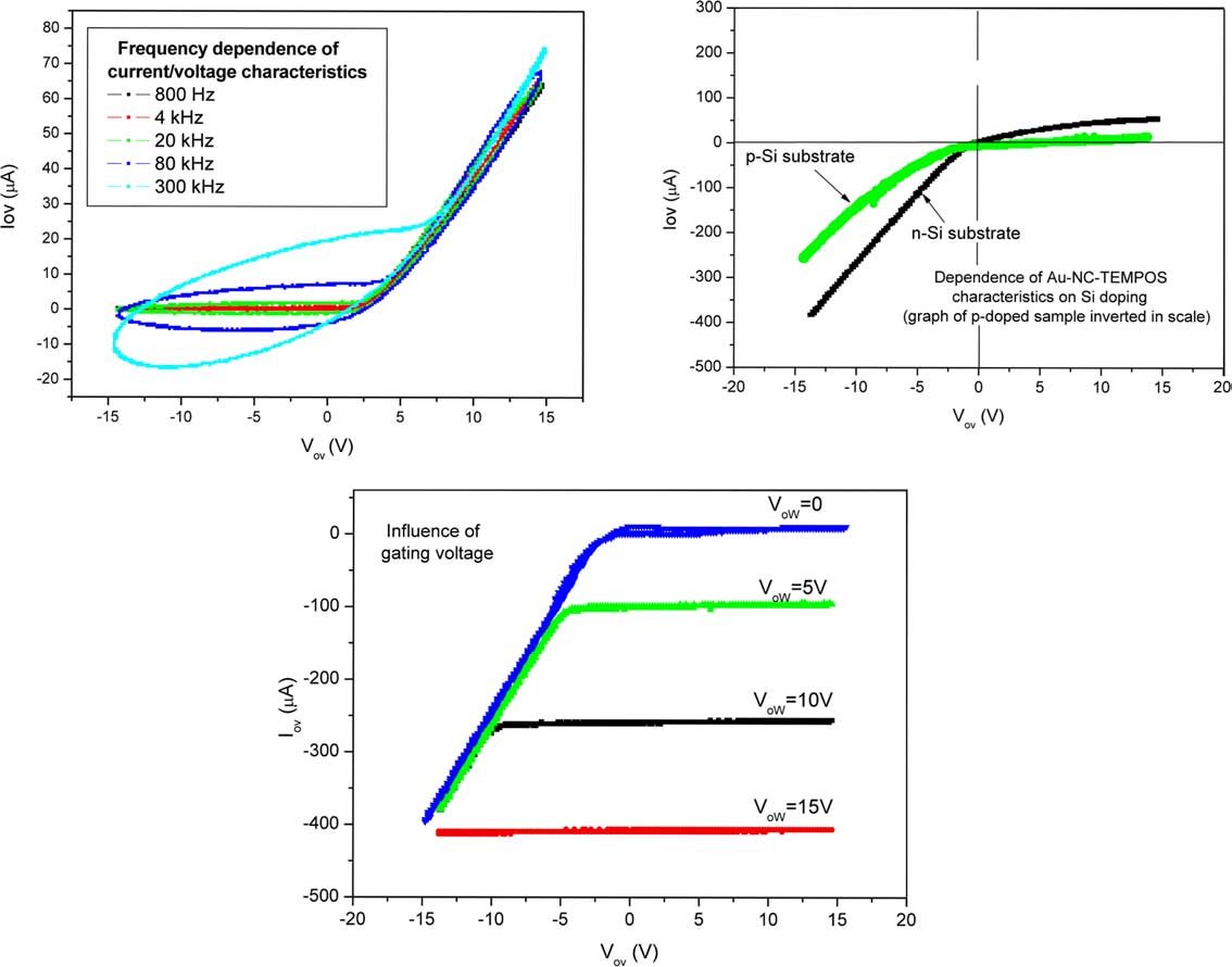
D. Fink et al. / Nucl. Instr. and Meth. in Phys. Res. B 236 (2005) 11–20 Fig. 4. Electrical characterisation of TEMIPOS structures with Au nanoclusters. Vov is the voltage applied from top (microporouspolymer layer; contact o) to bottom (Si substrate; contact v) of the TEMIPOS structure; Iov is the current measured along this path.
The gating voltage Vow is applied between the top contact o and another top contact w.
developer for 1 min at ambient temperature, and corresponding TEMPOS structures with SiO2 or then rinsed with water and dried. After depositing SiON dielectrica.
a droplet of distilled water onto that structureand contacting the latter with a tiny needle, anelectric current could be measured from the drop- let to the silicon substrate, thus indicating thefull track opening. Subsequently a droplet of a Ion tracks, specifically etched tracks, alone or 10% diluted commercial colloidal gold solution in combination with lithography, enable many was allowed to penetrate into the structure, and possibilities for creating novel deep micro-and nanostructures within polymer foils that are The contacted structure reveals electronic prop- difficult to produce or even inaccessible by other erties similarly to those ones prepared earlier, techniques. First prototypes of a number of ion We called it ‘‘TEMIPOS'', see above. The TEM- track-based electronic elements such as resistors, IPOS structures obtained thus far behave like tun- diodes, capacitors, magnets, transformers, tran- able diodes. Under some working conditions they sistors, and several types of sensors have been also show current instabilities ), as do the created, and the first hybride track-based silicon/ D. Fink et al. / Nucl. Instr. and Meth. in Phys. Res. B 236 (2005) 11–20 application of many of the topics touched herebriefly.
Finally it should be mentioned that self-order- ing thin porous ceramic foils, especially ofalumina, have emerged as serious competitors formicroporous polymer foils in many fields, due totheir higher temperature stability, higher rigidityand more regular pore arrangement. However,their brittleness, higher price and smaller size re-strict their applicability, so that the application po-tential of ion-track based microporous foils isnevertheless still tremendous.
We are indebted to Dr. P. Yu. Apel, JNRI Dub- na, to Dr. S. Klaumu¨nzer, Dr. J. Opitz-Coutureau,and the operators of the ISL accelerator, HMIBerlin, for enabling the swift heavy ion irradiationof other samples. This work was enabled withinthe frame of the ‘‘Strategiefonds Ionenspuren'' ofthe Helmholtz-Gesellschaft, Germany. Some ofus (D.F., P.S.A., A.V.P.) are obliged to theDAAD, and D.S. thanks the Indian governmentfor research grants in the frame ot the BOYS-CAST project that enabled this work.
[1] D. Fink, P.S. Alegaonkar, A.V. Petrov, A.S. Berdinsky, A.V. Rao, M. Mu¨ller, K.K. Dwivedi, L.T. Chadderton,The emergence of new ion track applications, Radiat.
Meas. 36 (2003) 605.
[2] D. Fink, R. Klett, Latent tracks in polymers for future use in nanoelectronics. an overview about the present state-of-the-art, Braz. J. Phys. 25 (1995) 54.
[3] G. Gebel, E. Ottomani, J.J. Allegrand, N. Betz, A.
LeMoel, Structural study of polystyrene grafted in irradi- Fig. 5. An example for the current instabilites found for ated polyvinylidene fluoride thin films, Nucl. Instr. and TEMIPOS structures. (a) Overall view of the current/voltage Meth. B 105 (1995) 145.
characteristics (150 Hz AC applied; zero gating voltage). (b) [4] A. Biswas, D.K. Awasthi, J. Kanzow, S.J. Ding, D. Fink, Detailed view of the instability region (10 cycles depicted); R. Gupta, V. Zaporojtchenko, F. Faupel, Nanostructural where reproducible jumps between a state ‘‘0'' and a state ‘‘1'' modifications in Au cluster arrays distributed in Teflon AF are observed. (c) The local differentiation of (b) reveals that the layers upon MeV heavy ion impact, to be published.
resistance in the instability region approaches to zero or even [5] S. Chakane, F. Singh, D.K. Avasthi, S.V. Bhoraskar, becomes negative, thus indicating the potential for applications Usefulness of nuclear tracks in polymers for hydrogen gas in active electronic devices.
sensing, in: 21st Int. Conf. on Nuclear Tracks in Solids,New Delhi, 21–25 October 2002.
polymer device has been tested successfully. It will [6] D. Fink, A. Petrov, N. Stolterfoht, M. Wilhelm, V.
be, however, still a long way up to the industrial Hoffmann, A. Richter, M. Behar, L. Farenzena, K. Hirata, D. Fink et al. / Nucl. Instr. and Meth. in Phys. Res. B 236 (2005) 11–20 L.T. Chadderton, A. Schulz, W.R. Fahrner, Creation of [20] D. Dobrev, R. Neumann, N. Angert, J. Vetter, Preparation nanoscale objects by swift heavy ion track manipulations, of metal membranes by direct electroplating of ion-track in: Proc. Int. Symp. on Material Chemistry in Nuclear filters, in: Proc. of the workshop on European Network on Environment, 13–15 March 2002, Tsukuba, Japan. Report Ion Track Technology, Caen, France, 24–26 February JAERI Conf. 2003-001, 2002.
[7] V. Herden, Das Verhalten von lichtinduzierten Lad- [21] C.R. Martin, Nanomaterials: a membrane-based synthetic ungstra¨gern in Polysilanen unter besonderer Beru¨cksichti- approach, Science 266 (1994) 1961.
[22] V.M. Cepak, J.C. Hulteen, G. Che, K.B. Jirage, B.B.
Vernetzung. Ph.D. Thesis, Technical University Berlin, Lakshmi, E.R. Fisher, C.R. Martin, Chemical strategies 2001. No. D83 (in German).
for template syntheses of composite in micro-and nano- [8] S. Seki, K. Maeda, Y. Yoskida, S. Tagawa, M. Sugim- structures, Chem. Mater. 9 (1997) 1065.
oto, S. Tanaka, Nano-wire formation along ion projec- [23] C.R. Martin, Template synthesis of polymeric and metal tiles in polysilane thin films, JAERI-Review G39 125 microtubules, Adv. Mater. 3 (1991) 457.
[24] Z. Cai, C.R. Martin, Electronically conductive polymer [9] S. Seki, S. Tsukuda, Y. Yoshida, T. Kozawa, S. Tagawa, M. Sugimoto, S. Tanaka, Nanowire formation and selec- electronic conductivities, J. Am. Chem. Soc. 111 (1989) tive adhesion on substrates by single-ion track reaction in polysilanes, Jpn. J. Appl. Phys. 42 (2003) 4159.
[25] C.J. Brumlik, V.P. Menon, C.R. Martin, Template syn- [10] S. Tsukuda, S. Seki, S. Tagawa, M. Sugimoto, A. Idesaki, thesis of microtubule ensembles utilizing chemical, electro- S. Tanaka, Fabrication of nanowires using high-energy ion chemical, and vacuum deposition techniques, J. Mater.
beams, J. Phys. Chem. B 108 (2004) 3407.
Res. 9 (1994) 1174.
[11] S. Tsukuda, S. Seki, A. Saeki, T. Kozawa, S. Tagawa, M.
[26] K. Liu, N. Nagodawithana, P.C. Searson, C.L. Chien, Sugimoto, A. Idesaki, S. Tanaka, Precise control of Perpendicular giant magnetoresis tance of multilayered Co/ nanowire formation based on polysilane for photoelec- Cu nanowires, Phys. Rev. B 51 (1995) 7381.
tronic device application, Jpn. J. Appl. Phys. 43 (2004) [27] A. Biswas, D.K. Awasthi, B.K. Singh, S. Lotha, J.P.
Singh, D. Fink, B.K. Yadav, B. Bhattacharya, S.K. Bose, [12] D. Fink, D. Sinha, A. Petrov, J. Opitz-Coutureau, W.R.
Resonant electron tunneling in single quantum well Fahrner, K. Hoppe, L.T. Chadderton, A.S. Berdinsky, heterostructure junction of electrodeposited metal semi- Nanotechnology with ion track-tailored media, in: Proc.
conductor nanostructures using nuclear track filters, Nucl.
Intl. Conf. on Nanotechnology, Minsk, May 2005.
Instr. and Meth. B 151 (1999) 84.
[13] D. Fink, A.S. Berdinsky, L.T. Chadderton, W.R. Fahrner, [28] J.D. Klein, R.D. Herrick II, D. Palmer, M.J. Sailor, C.J.
Brumlik, C.R. Martin, Electrochemical fabrication of tropic Materials on Semiconductors (TEAMS), to be pub- cadmium chalcogenide microdiode arrays, Chem. Mater.
5 (1993) 902.
[14] J. Krauser, A. Weidinger, J.H. Zollondz, B. Schultrich, H.
[29] R.P. Burford, T. Tongtam, Conducting polymer with Hofsa¨ss, B. Ronning, Conducting ion tracks for field controlled fibrillar morphology, J. Mater. Sci. 26 (1991) emission, in: Proc. Workshop on the European Network 3264, and references therein.
on Ion Track Technology, Caen, France, 24–26 February [30] D. Fink (Ed.), Transport Processes in Ion Irradiated Polymers and Applications, Springer Series in Materials [15] J.C. Hulteen, C.R. Martin, Template synthesis of nano- Science, Vol. 65, Springer-Verlag, 2004.
particles in nanoporous membranes, in: J.H. Fendler (Ed.), [31] J.D. Klein, R.D. Herrick II, D. Palmer, M.J. Sailor, C.J.
Nanoparticles and Nanostructured Films, Wiley-VCH, Brumlik, C.R. Martin, Electrochemical fabrication of Weinheim, 1998, p. 235 (Chapter 10).
cadmium chalcogenide microdiode arrays, Chem. Mater.
[16] D. Dobrev, J. Vetter, R. Neumann, Growth of potassium 5 (1993) 902.
iodide single-crystals using ion track membranes as tem- [32] S.K. Chakarvati, J. Vetter, Microfabrication of metal- plates, Nucl. Instr. and Meth. B 146 (1998) 513.
semiconductor heterostructures and tubules using nuclear [17] A.S. Berdinsky, D. Fink, A.V. Petrov, M. Mu¨ller, L.T.
track filters, J. Micromech. Microeng. 3 (1993) 57.
Chadderton, J.F. Chubaci, M.H. Tabacnics, Formation [33] M. Berggren, O. Ingana¨s, Micrometer- and nanometer- and conductive properties of fullerite in etched ion tracks sized polymeric light-emitting diodes, Science 267 (1995) in a polymer film, in: Proc MRS Fall Meeting, Boston 27.11.-1.12. 2001, Contribution Y4.7.
[34] J.H. Scho¨n, A. Dodabalapur, Ch. Kloc, B. Batlogg, A [18] A. Petrov, Production of micro- and nanoelectrotechnic light-emitting field-effect transistor, Science 290 (2000) 963.
devices based on ion tracks in insulators. Ph.D. Thesis [35] J.D. Klein, R.D. Herrick, D. Palmer, M.J. Sailor, Electro- Fernuniversita¨t Hagen, Germany, 2004.
chemical fabrication of cadmium chalcogenide microdiode [19] T.M. Whitney, J.S. Jiang, P.C. Searson, C.L. Chien, arrays, Chem. Mater. 5 (1993) 902.
Fabrication and magnetic properties of arrays of metallic [36] J. Chen, S. Klaumu¨nzer, M.C. Lux-Steiner, R. Ko¨nenk- nanowires, Science 261 (1993) 1316.
amp, Appl. Phys. Lett. 85 (2004) 1401.
D. Fink et al. / Nucl. Instr. and Meth. in Phys. Res. B 236 (2005) 11–20 [37] R. Ko¨nenkamp, J. Chen, S. Klaumu¨nzer, R. Engelhardt, [51] J.D. Klein, R.D. Herrick II, D. Palmer, M.J. Sailor, C.J.
Mater. Res. Soc. Symp. Proc. Vol. 814, I7.4.1.
Brumlik, C.R. Martin, Electrochemical fabrication of [38] J. Chen, R. Ko¨nenkamp, Appl. Phys. Lett. 82 (2003) 4782.
cadmium chalcogenide microdiode arrays, Chem. Mater.
[39] J. Chen, S. Klaumu¨nzer, R. Ko¨nenkamp, Mater. Res. Soc.
5 (1993) 902.
Symp. Proc., Vol. 777.
[52] R.V. Parthasarathy, C.R. Martin, Synthesis of polymeric [40] C.R. Martin, M. Nishizawa, K. Jirage, M. Kang, S.B.
microcapsule arrays and their use for enzyme immobiliza- Lee, Controlling ion-transport selectivity in gold nanotu- tion, Nature 369 (1994) 298.
bule membranes, Adv. Mater. 13 (2001) 1351.
[53] M.G.R. Rajan, B. Gupta, Immobilisation of antibody [41] M. Tamada, M. Yoshida, M. Asano, H. Omichi, R.
spots on glass surfaces- potential use as antibody chips for Kakakai, R. Spohr, J. Vetter, Thermoresponse of ion multianalyte assay, in: Paper presented at the 9th Asia track pores in copolymer films of methacryloyl-L-alanine Pacific Conference on clinical biochemist, New Delhi, methyl ester and diethylene glycol bisallyl carbonate, March 2002; and: Rajan MGR, Bharati Gupta, Iyer RH, Polymers 33 (1992) 3169.
Samuel AM, Track-etched membranes–a novel substrate [42] K. Hjort,The European network on ion track technology, for ‘‘antibody chips'' for multi analyte immunoassays.
in: Presented at the 5th Int. Symposium on ‘‘Swift Heavy Presented in: Nuclear and Radiochemistry symposium, Ions in Matter'', Giordano Naxos, Italy, 22–25 May 2002.
BARC, Mumbai, India, 10–13 February 2003.
[43] M. Lindeberg, L. Gravier, J.P. Ansermet, K. Hjort, [54] D. Fink, A. Petrov, J. Rojas-Chapana, H. Tributsch, D.
Processing magnetic field sensors based on magnetoresis- Friedrich, U. Ku¨ppers, M. Wilhelm, P.Yu. Apel, A.
tive ion track defined nanowire cluster links, in: Proc. of Zrineh, The ‘‘Artificial Ostrich Eggshell Project: sterilizing the workshop on European Network on Ion Track polymer foils for food industry and medicine, in: Proc. 8th Technology, Caen, France, 24–26 February 2002.
Int. Conf. on Condensed Matter and Statistical Physics, [44] SDK Technik GmbH, Gro¨pern 25, D-06484 Quedlinburg Marrakech-Morocco, 21–24 September 2004.
[55] R. Pool, Physicists tackle theory, tubes, and temperature, [45] RoTracÒ Capillary pore membranes. Information leaflet Science 247 (1990) 1410.
of Oxyphen GmbH Dresden, Rossendorfer Technologie- [56] L. Gravier, T. Ohgai, A. Fabian, T. Wade, J.E. Wegrowe, zentrum, Bautzener Landstr. 45, D-01454 Grosserkmanns- J.P. Ansermet, Magnetoresistance and magnetothermo- dorf, Germany (2001).
power of magnetic nanowires, in: Proc. of the workshop on [46] M. Renardy, H. Planck, J. Trauter, P. Zschocke, U.
European Network on Ion Track Technology, Caen, Siebers, T. Zecorn, K. Federlin, in: G. Heime, U. Solte´sz, France, 24–26 February 2002.
A.J.C. Lee (Eds.), Clinical Implant Material, Adv.
[57] A.V. Petrov, S.E. Demyanov, D. Fink, W.R. Fahrner, Biomat., Vol. 9, 1990, p. 633.
A.K. Fedotov, P.S. Alegaonkar, A.S. Berdinsky, Novel [47] M. Nishizawa, K. Mukai, S. Kuwabata, C.R. Martin, H.
electronic devices for nanotechnology based on materials Yoneyama, Template synthesis of polypyrrole-coated spi- with ion tracks, in: Proc. Intl. Conf. on Nanotechnology, nel LiMn2O4 nanotubules and their properties as cathode Minsk, May 2005.
active materials for lithium batteries, J. Electrochem. Soc.
[58] K. Hjort, Ion track technologies and device fabrication.
144 (1997) 1923.
Proceedings of these conference.
[48] A.S. Berdinsky, Yu.V. Shevtsov, A.V. Okotrub, S.V.
[59] D. Fink, A. Petrov, H. Hoppe, A.G. Ulyashin, R.M.
Tombin, L.T. Chadderton, D. Fink, J.M. Lee, Sensor Papaleo, A. Berdinsky, W.R. Fahrner, Etched ion tracks properties of fullerene films and fullerene compounds with in silicon oxide and silicon oxynitride as charge injection iodine, Chem. Sustainable Dev. 8 (2000) 141.
channels for novel electronic structures, Nucl. Instr. and [49] A. Berdinsky, D. Fink, M. Mu¨ller, A. Petrov, L.T.
Meth. B 218 (2004) 355.
Chadderton, P.Y. Apel, Formation and conductive prop- [60] L.-M. Wang, R. Fromknecht, L. Snead, D.F. Downey, H.
erties of miniaturized fullerite sensors, in: Proc MRS Takahasi (Eds.), Characterization of ‘‘TEMPOS'': A new Boston, Fall meeting, 27.11.-1.12.2001; Contribution Y4.7.
Tunable Electronic Material with Pores in Oxide on [50] M. Delvaux, P.-Y. Stavaux, L. Dauginet-de-Pra, F.
Silicon. MRS Fall Meeting Proceedings, Vol. 792, R 7.9.
Dehaye, S. Cuenot, S. Demoustier-Champagne, B. Nysten, [61] D. Fink, A.V. Petrov, W.R. Fahrner, K. Hoppe, R.M.
E. Ferain, R. Legras, Chemical modifications induced in Papaleo, A.S. Berdinsky, A. Chandra, A. Zrineh, L.T.
bisphenol A polycarbonate by swift heavy ions, in: Chadderton, Ion Track Based Nanoelectronics, in: Proc.
Presented at the 5th Int. Symposium on ‘‘Swift Heavy Int. Conf. on Nano Science and Technology, Kolkata Ions in Matter'', 22–25 May 2002, Giordano Naxos, Italy.
(India), 15–21 December 2003.

Source: http://cryogenic.physics.by/download/publications/article/High%20energy%20ion%20beam%20irradiation%20of%20polymers%20for%20electronic%20applications_2005.pdf

humboldt.org.ni

DENUNCIA CIUDADANA Señora Ruth Obando, Delegada Departamental del Ministerio del Ambiente y Recursos Naturales del Departamento de Chontales. Nosotros los abajo firmantes, ciudadanos y ciudadanas nicaragüenses todos mayores de edad, domiciliados en los municipios de Santo Domingo y Managua amparados en el artículo 2 de la Ley 217, Ley General de Medio Ambiente y los Recursos Naturales, que establece que toda

psychsustain.voices.wooster.edu

Critical Reviews in Toxicology, 2010; 40(4): 287–304 Critical Reviews in Toxicology Pharmaceuticals in the aquatic environment: A critical review of the evidence for health effects in fish Jenna Corcoran1, Matthew J� Winter2, and Charles R� Tyler1 1Environmental and Molecular Fish Biology, School of Biosciences, The Hatherly Laboratories, University of Exeter, Exeter, Devon, UK, and 2AstraZeneca Safety, Health and Environment, Brixham Environmental Laboratory, Freshwater Quarry, Brixham, UK