
Cialis ist bekannt für seine lange Wirkdauer von bis zu 36 Stunden. Dadurch unterscheidet es sich deutlich von Viagra. Viele Schweizer vergleichen daher Preise und schauen nach Angeboten unter dem Begriff cialis generika schweiz, da Generika erschwinglicher sind.
Doi:10.1016/j.colsurfa.2006.02.066
Colloids and Surfaces A: Physicochem. Eng. Aspects 286 (2006) 39–50
Surfactant mediated adsorption of negatively charged latex
particles to a cellulose surface
L. Schaffner a, G. Br¨ugger a, R. Nyffenegger a, R. Walter a,
J. Riˇcka a
,∗, J. Kleimann b, J. Hotz c, Ch. Quellet c
a
Institute of Applied Physics, Department of Biomedical Photonics, University of Bern, Sidlerstrasse 5, CH-3012 Bern, Switzerland
b
Department of Inorganic, Analytical, and Applied Chemistry, University of Geneva, Science II,
30 Quai Ernest Ansermet, CH-1211 Geneva 4, Switzerland
c
Fragrance Research/Delivery Systems, Givaudan Schweiz AG, CH-8600 D¨ubendorf, Switzerland
Received 5 December 2005; received in revised form 16 February 2006; accepted 28 February 2006
Available online 18 April 2006
The adsorption of anionic, carboxyl functionalized latex particles, recharged by a cationic surfactant acting as fabric softener/conditioner, to a
cellulose surface was investigated with evanescent wave video microscopy. This technique allows to monitor the deposition and release of individualparticles in real-time with an excellent selectivity and sensitivity. Since the recharged particles and the conditioner compete for the free surface,the initial deposition rate and final surface coverage are found to be strongly dependent on the ratio of particle and conditioner concentrations.
2006 Elsevier B.V. All rights reserved.
Keywords: Cellulose; Evanescent wave microscopy; Particle deposition; Cationic surfactant; Adsorption; Recharging; Competitive adsorption
and desorption processes. The adsorption kinetics of polymerlatex and cationic surfactants on their own have been investigated
The addition of specially modified polymer particles to laun-
in great detail in respectively.
dry detergents and conditioners offers an interesting way to pro-
In this paper, we report the use of a "micro laundry" cell and
vide functional ingredients, such as bioactive substances, to tex-
the technique of evanescent wave video microscopy (EWVM)
tile fabrics during laundering, allowing them to be released over
to investigate in real-time the deposition and release of fluo-
a prolonged period of time after the wash, rinse and drying pro-
rescent latex particles on a flat cellulose surface during a sim-
cesses have been completed. To fulfill this task, the particles
ulated laundering cycle. The micro laundry cell provides an
must deposit to a significant extent and remain on the fabric
environment for monitoring the dynamics of particles under
during drying, storage and use by consumers. In this paper, we
laminar shear flow conditions in the immediate vicinity of the
consider the case of conditioner-mediated adsorption of latex
particles during the rinsing phase.
Videomicroscopy is an established and powerful technique
The magnitude of the desired effect is directly related to the
in colloid science and, thanks to the improvement in sensitivity
number of particles that remain adsorbed on the fabrics after
and resolution of CCD cameras, able to provide more and more
the final rinsing and drying phases. However, another important
information about the adsorption process involved (see
requirement is the ability of depleted particles to be removed
references therein). The EWVM-technique requires substrates
during a subsequent wash cycle. To achieve this behaviour and
having a good optical flatness and transparency, which is not the
optimize the balance between deposition and removability, it is
case for conventional textile fabrics. Hence, for this study, we
necessary to understand the factors underlying both deposition
use a cellulose film to mimic cotton which is of special interestfor our application as cotton is the most commonly used fabricmaterial worldwide. The interaction of colloidal particles with
∗ Corresponding author. Tel.: +41 31 631 8904.
cellulose surfaces is also of considerable interest in paper making
E-mail address: (J. Riˇcka).
0927-7757/$ – see front matter 2006 Elsevier B.V. All rights reserved.
doi:
L. Schaffner et al. / Colloids and Surfaces A: Physicochem. Eng. Aspects 286 (2006) 39–50
Principally, both positively and negatively charged latex par-
ticles can be used in the process. In the case of negatively chargedparticles, however, the interactions with the initially negativelycharged cellulose are a priori not favorable for particle adsorp-tion. This study shows that the cationic surfactant present in theconditioner forms a complex with the anionic particles, whichleads to charge inversion and allows deposition of the particles.
However, during the rinsing phase, the remaining free surfactant
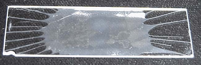
Fig. 1. Cellulose film spin-cast onto a quartz substrate. The image was taken
compete with the afore mentioned complex for the free cellu-
after evaporation of the DMA solvent but before washing out remaining LiCl
lose surface, thus making the system extremely sensitive to the
crystals with deionized water, after which the film becomes nearly transparent.
relative and absolute concentrations of latex particles and sur-factant. Such competitive adsorption has also been investigated
the adhesion of a new cellulose coating. However, the chromic
acid treatment requires subsequent removing of all chromiumtraces by submerging the substrates in 1 M hydrochloric acid
2. Materials and methods
for 1 h. Again, the acid treatment was followed by rinsing withdeionized water. Finally the excess water was blown away with
2.1. Preparation and characterization of the model
nitrogen and the substrates were dried in an oven at 90 ◦C for
After cooling down to room temperature, the substrate was
Since the EWVM technique requires a reasonable optical
placed on the spin casting apparatus, consisting of a dc motor
flatness and transparency of the probed surface, a spin casting
and a rotating disk where the substrate may be mounted. To pro-
technique was used to produce a thin film of cellulose on a
duce a film, an aliquot of about 32 mg cellulose solution was
quartz glass substrate We used a 5 g/l cellulose solution
dropped onto the center of the rotating quartz substrate with a
which was obtained by dissolving cellulose powder (supplier:
standard 1 ml syringe. The dc motor was driven at constant rota-
Fluka Switzerland, acid-washed from cotton linters, degree of
tion frequency of about 3000 rpm. Thirty seconds after placing
polymerization: 1400) in a mixture of N,N-dimethylacetamide
the drop the power was cut and the plate was left spinning until
(DMA, supplier: Merck, for synthesis) and lithium chloride
(LiCl, supplier: Merck, pro analysis). All chemicals had to
Next, the substrate was placed in the oven again (90 ◦C, 2 h),
be dried before use. DMA was dried with a molecular sieve
in order to evaporate the cellulose solvent. However, at this stage
(0.3 nm). LiCl and the cellulose powder were dried at elevated
some LiCl always remains in the cellulose film, probably in the
temperature in vacuum for 2 h. The temperature was set to 130
form of small crystals which give the film a visible opacity. By
and 100 ◦C for LiCl and cellulose, respectively.
carefully soaking the substrate in a beaker with flowing deion-
To dissolve the cellulose, 0.5 g of the powder were first dis-
ized water for 10 min the LiCl can be washed out without peeling
solved in 94 g DMA for 2 h at a temperature of 130 ◦C while
away the still very fragile cellulose film. After a final drying in
stirring under dry argon in a closed vessel. To achieve a complete
the oven (90 ◦C, 1 h) the cellulose surface was almost transpar-
dissolution, 10 g LiCl at a temperature of 100 ◦C were added.
ent and showed sufficient adhesion as not to be washed away
(This is method A described in ut using a ten times higher
when performing the flow cell experiments.
LiCl concentration with respect to the cellulose.) After letting
The thickness of the cellulose layer was estimated with scan-
the solution cool down to room temperature under constant stir-
ning angle null ellipsometry A typical value was 50 nm,
ring, it was filtered (again under dry argon) through a 0.5 m
but the actual thickness may vary from sample to sample. The
PTFE-membrane to remove LiCl crystals that had formed during
technique also allows the determination of the refractive index.
The resulting value of 1.49 at a wavelength of 633 nm is in good
Prior to spin casting, the quartz substrates were submerged in
agreement with literature
chromic acid for 1 h, followed by rinsing with deionized water.
The surface structure of the cellulose films was investigated
The acid treatment was necessary to completely remove residual
by atomic force microscopy in tapping mode. As can be seen in
surfactant molecules and other impurities which could impair
the surface of films spin cast from DMA/LiCl solutionis quite homogeneous and flat over large areas. At nanometer-scales, however, a characteristic texture appears (
1 A second cellulose solvent system consisting of a mixture of N-
Note that the scale on the horizontal axis is different from the
methylmorpholine-N-oxide (NMMNO) and dimethyl sulfoxide (DMSO) was
scale on the vertical axis. While the typical horizontal dimen-
tested but found to be unsuitable, even though the cellulose was dissolved muchmore easily and efficiently, because the resulting spin cast cellulose surfaces
sions of the characteristic dips and peaks on the surface are on
did not adhere well to the quartz substrate and peeled off easily. In addition the
the order of 200 nm, vertical irregularities probed by the AFM
surface turned out to be much rougher than with cellulose dissolved in DMA
tip are not larger than about 20 nm. However, as the AFM profile
which lessened contrast with the EWVM-technique considerably. Furthermore,
is a convolution of the real surface with the AFM tip this
the cellulose solution turned out to be unstable, evidenced by a slow change of
does not exclude the existence of up and down structures that
color to brown and eventually showing precipitate of cellulose after approxi-mately 8 days, making it necessary to prepare the solution freshly before each
are deeper and narrower than the height and width of the tip. The
origin of the nanoscale structure of the cellulose films remains


L. Schaffner et al. / Colloids and Surfaces A: Physicochem. Eng. Aspects 286 (2006) 39–50
Fig. 3. AFM image of the surface topography of model fabric made of cotton.
The observed area was 2 m ×2 m.
process applied and the cellulose surface can only provide anapproximation of the real textile surface at micrometer lengthscales. In particular the possible influence of the micro-fibersoccurring on natural cotton fibers cannot be investigated withthis model. Nevertheless, cellulose appears to be the simplestavailable model for the present study, combining chemical sim-ilarities with cotton fibers and a given surface structure, whilestill showing an acceptable optical transparency, as required bythe measurement set-up.
2.2. Latex particles
Fig. 2. AFM images of spin-cast cellulose films: (top) AFM picture of a cellulose
The anionic carboxylated polystyrene latex spheres used in
film coated from a DMA/LiCl solution on a quartz substrate (observed area:
our measurements were custom-synthesized by in-situ emul-
100 m ×100 m) and (bottom) Nanoscale structure of the cellulose coating
sion polymerization of styrene and methacrylic monomers in
(observed area: 2 m ×2 m).
the presence of both the active substance ingredients and flu-
unexplained, as is the role of adhesion in the generation of these
orescent probe molecules. After considering and testing many
structures. We assume that the characteristic dips and peaks ob-
different fluorescent dyes, fluorescent Yellow 3G (FY3G) was
served in films casted from LiCl/DMA solutions is due to the
chosen since it shows good incorporation into the particles and
formation of small LiCl crystals during solvent evaporation.
is expected to reside mainly in the outer shell of the polystyrene
This cellulose surface is to be compared with the surface of
spheres, owing to its amphiphilic character. The final particle
real textile fabric. The architecture and superstructure of com-
suspension had a solid content of 43.22 g/ml and a polymer con-
mon fabrics can be understood in terms of a well-organized hier-
tent of 35.8 g/ml. The latter was used for the calculation of the
archy of fibrillar entities is built-up of micro-fibers
number of particles.
(so called fibrilla) which assemble to form the cotton fiber itself.
We determined the hydrodynamic radius and the radius of
This smallest morphological unit has a diameter in the range of
gyration by dynamic and static light scattering on a ALVCGS-
3–20 nm, depending on the origin of the cellulose. ws
8F light scattering instrument (ALV GmbH) at a wavelength of
an AFM image of a model fabric made of cotton. At the first
532 nm. The particle diameters were found to be 232 nm (hydro-
glance the surface structure is not very similar to our spin-cast
dynamic) or 228 nm (gyration) with a polydispersity of 9%. Par-
cellulose films. However, while the surface topography of cotton
ticle charge densities were determined through electrophoretic
is smoother and seems to be ordered along one direction in com-
mobility measurements at different ionic strengths, based on the
parison to our cellulose surface, the height of the characteristic
theory developed by O'Brien and White resulting sur-
surface structures is still of similar magnitude (20 nm).
face charge was found to be (40 ± 5) mC/m2.
While cellulose is the main constituent of cotton, it must be
w high resolution pictures of particles ad-
kept in mind that the range of different textile fabrics is very
sorbed to the surface obtained with electron and atomic force
broad and significant amounts of other chemicals used during
microscopy. The quartz substrates were investigated after a par-
finishing processes may also be present on or in these mate-
ticle deposition measurement on the cellulose. The particle di-
rials. In addition to that, the structure and surface of the tex-
ameter, as determined from the electron microscopic image in
tile fibers may vary significantly depending on the production
well with the one determined by light scattering.


L. Schaffner et al. / Colloids and Surfaces A: Physicochem. Eng. Aspects 286 (2006) 39–50
preventing the gelation of Rewoquat aggregates (lamellae, lipo-somes).
Laundering is usually done with the local tap water of vary-
ing ionic strength and mineral content. To be closer to real-lifewhile maintaining standard conditions, we used a standardizedtap water consisting of a 1 mM CaSO4 in deionized water (fromnow on referred to as "tap water"). This solution was also usedfor rinsing the cellulose surface during the simulated launderingcycles.
Samples of varying particle and conditioner concentrations
were prepared by mixing the desired amount of the primaryparticle suspension described in the previous section with theconditioner and tap water.
2.4. Evanescent wave video-microscopy (EWVM)
ws the setup employed for the measurements. De-
tails on the optical features and data evaluation procedures, in-
Fig. 4. Electron microscope image of particles adsorbed to cellulose surface. Theparticles appear bigger than they actually are due to being covered with a gold
cluding corrections for the limited optical and finite time resolu-
surface of around 30 nm thickness for the EM-imaging. The quartz substrate was
tion are discussed in detail elsewhere The technique allows
investigated after a particle deposition measurement with a conditioner concen-
the detection of individual particles adhering to the probed sur-
tration of 1.0 × 10⁻⁴ g/ml and a particle concentration of 0.94 × 10¹⁰/ml. The
face with an excellent sensitivity and selectivity. The surface
final surface coverage was determined from the EM-image to 682 × 103/mm2
coverage, the influx and outflux of the particles to and from the
and with the EWVM-technique to 631 × 103/mm2. This represents 2/3 of thehighest coverage we have found in our experiments.
surface, as well as the distribution of times the particles spend onthe surface can be monitored in real-time, providing a detailed
The image also indicates that the colloids may get close and
analysis of the dynamics of particle/substrate exchanges.
eventually form aggregates on the surface. Also the height de-
A Lexel 85 argon-ion laser with a power of 150 mW (of
termined by AFM agrees reasonably well with the measured
which 44 mW remain after coupling through the single mode
particle diameters, but sometimes the particle may penetrate the
fiber mentioned below) at a wavelength of 488 nm serves as
surface as shown in
light source for the evanescent wave illumination. The laserbeam is coupled to a single mode fiber, whose other end is
2.3. Conditioner and standard tap water
fixed on a rotating arm to allow adjusting the angle of incidenceon the prism and thus indirectly the angle of incidence at the
Stock solution of conditioner was obtained by mixing 5 g
glass/cellulose–water interface θi. As long as this angle is
of dihydrogenated Tallowethylammonium methosulfate (Re-
higher than the critical angle of total internal reflection θc (For
woquat WE 18, supplied by Degussa) and 0.5 g of a mixture of
the quartz–water interface θc = 47.7◦) an evanescent wave will
C9–C11 linear fatty alcohol - polyethylene glycol ethers having
be generated with an intensity decaying exponentially away
an average content of 8 mol ethylene oxide per mole of alco-
from the interface with a typical length of a few dozen nm.
hol (Neodol 91-8E, ex Shell) and 94.5 ml deionized water. The
The exact depth δ can be adjusted by the angle of incidence
active substance is the cationic surfactant Rewoquat, a quater-
θi our case δ = 141 nm, which is in the range of the
nary esther of triethanolamine. Neodol acts as a colloid stabilizer
particle radius. Because of the small penetration depth of
Fig. 6. Evanescent Wave Video Microscopy Setup. A flow cell, fed by a sy-ringe pump and incorporated into a modified Zeiss Axiovert 100TV inverted
Fig. 5. Atomic force microscope image of single adsorbed particle. Observed
microscope allows to observe particle adsorption and desorption to a glass–
area: 2 m × 2 µm.
cellulose/water interface illuminated by an evanescent wave in real-time.

L. Schaffner et al. / Colloids and Surfaces A: Physicochem. Eng. Aspects 286 (2006) 39–50
the evanescent wave, only particles adsorbed to the cellulosesurface film on the quartz substrate are illuminated (To better discriminate the particles from surface structures ofcomparable size they are additionally fluorescently labelled.
The fluorescence light emitted from the particles is guided
along the optical paths of the microscope (a Zeiss Axiovert100TV) and can either be observed through the eyepiece orrecorded with a digital CCD camera (Kappa CF 8/1 DX). Anedge filter was set in the optical path to filter out scattered laserlight. The CCD camera is controlled by a computer which alsosteers a shutter that is only opened when recording a picture tominimize bleaching of the fluorescent dye. The resulting highsensitivity and selectivity allows to monitor the individual ad-sorption and desorption of each single particle. We are thus able
Fig. 7. Parallel plate flow cell setup. Particles adsorbed to the cellulose surface
to record the number of resident particles R(t) on the observed
are illuminated by the evanescent wave generated by the total internal reflection
area as a function of time.
at the glass/cellulose–water interface. The prism above the upper plate is nec-essary to achieve reflection angles above the critical angle on the glass–water
2.5. Sample cell: micro laundry
The dynamics of adsorption and removal of latex particles
certain length lcrit = 0.044 × Re × 2h in order for all influences
during both rinse and wash cycles are expected to be governed
of the inlet to dissipate and laminar flow to develop. With a
by two groups of physico-chemical factors. The first group deals
flow cell of dimensions 2h = 0.55 mm (thickness), w = 8 mm
with particle–substrate interactions and encompasses attractive
(width), l = 45 mm (length) and a flow rate of Q = 1 ml/min
van der Waals forces, repulsive or attractive electrostatic forces
both criteria are fulfilled.
and steric interactions with the substrate and/or with other ad-sorbed species such as surfactants. The second group deals with
2.6. Laundering cycle
the transport of the particles to and from the surface which resultsfrom the interplay of diffusion and advection of the particles in
The idea behind our micro laundry was to mimic the ac-
the flowing liquid.
tual laundering process of a common laundry machine. This
Even though the flow field in a real laundry machine is ex-
usually involves a sequence of three basic processes: During
tremely complex, the dynamics of attachment and detachment
the main wash the textile fabric is cleaned with detergent at
of the latex particles is governed by processes taking place
a chosen temperature. This is followed by several rinse/spin
in a very thin layer of fluid adjacent to the textile fiber sur-
cycles with water where detergent and soil are removed. Dur-
face, which justifies splitting up the hydrodynamic processes
ing a final rinsing (conditioning) the conditioner is added to
into two components, specifically laminar shear flow parallel
the water and its cationic surfactant deposits onto the textiles.
to the surface and a jet flow impinging perpendicularly to the
Since, in the present study, the conditioner was the preferred
medium for the particle deposition, special attention was paid
Both types require their own flow cell geometry, a parallel
to the conditioning cycle. In particular, the effect of condi-
plate chamber with laminar shear flow perpendicular to the ob-
tioner to particle concentration ratio were investigated in order
served surface or a stagnation point flow cell with a jet flow
to achieve a high final coverage of particles on the cellulose
impinging perpendicularly on the probed surface, respectively.
For this paper we have concentrated mainly on the laminar flow
The micro laundry flow cell can be used to simulate the tran-
conditions, since the parallel plate cell has already been used and
sition from wash cycle to rinse and conditioning cycle by simply
tested extensively additional measurements with the
switching the fluid feed from a detergent solution (4% Deconex,
impinging jet cell have been made, but comparing the results
supplied by Borer Chemie AG, in deionized water) to tap water
with those achieved under laminar flow conditions yield a very
and then to a conditioner/latex mixture as described above. By
similar adsorption behaviour concerning final particle coverage.
turning the feed back to detergent the removal of deposited par-
The main difference is that the saturation level is reached much
ticles during subsequent wash cycles can be investigated. This
earlier, so that the initial particle deposition rate is higher by a
whole simulated laundering cycle can be repeated several times.
factor of up to ten.
As it was shown that a few particles (up to 60 on the observed
A predefined mixture of latex, conditioner and tap water is
area of 200 m ×150 m) always remained on the surface even
pumped with constant velocity trough the flow cell. Thus, the
after flushing with Deconex, the cellulose surface substrate has
mixture always acts on the "laundry load" (cellulose film) in a
to be replaced after 5–10 simulated laundering cycles. Also in
well defined flow pattern imposed by the geometry of the sample
some rare cases the cellulose surface itself peeled away from the
cell. There are two main pre-conditions for laminar flow
quartz substrate.
first the Reynold's number Re must be well below 2000 and
All experiments were conducted at room temperature (20 ◦C),
second, according to the chamber length l must exceed a
the flow rate was set to Q = 1 ml/min. This is a discrepancy to

L. Schaffner et al. / Colloids and Surfaces A: Physicochem. Eng. Aspects 286 (2006) 39–50
a real wash cycle where usually temperatures of 45, 60 or even90 ◦C are used. However, using higher temperatures did not onlyimprove the removal of the latex particles but also of the cellulosefilm itself.
2.7. Measurement procedure
With the EWVM-technique we now recorded the number
of particles adsorbed to the cellulose surface, R(t), during thesimulated conditioning cycle. Observations were done with a20× objective (Zeiss LD A-Plan, N.A. 0.3) which resulted inan observed area A of 200 m ×150 m on the cellulose film.
The chosen magnification is a compromise between the opti-cal resolution and the field of view required for a sufficientcounting statistics. However, when the distance between the ad-
Fig. 8. Example of a typical measurement. Particle concentration: 0.94 ×
sorbed particles decreases below the resolution, the spots rep-
1010/ml, conditioner concentration: 1.0 × 10⁻⁴ g/ml. The two grayscale images
resenting the particles overlap and the counting algorithm be-
show pictures taken with an exposure time of 210 ms and an observed area of
gins to fail. Eventually the CCD sensor becomes overexposed.
200 m ×150 m. Since the counting algorithm will fail for too dense cover-ages (right grayscale image) the integral fluorescent signal from whole observed
To overcome this problem we record the images alternatingly
area was alternatingly recorded to determine the final coverage.
with an exposure time of 4 and 210 ms and combine two eval-uation techniques: pictures recorded with the longer exposuretime allow us to count the adsorbed particles directly from the
rameters of interest are the initial deposition rate ˙
Γ (0) (deter-
image with the counting algorithm the short expo-
mined from the particle counting) and the final coverage Γ (∞)
sure time is used to simply monitor the change in the overall
(derived from the integral intensity measurements).
intensity, which is also proportional to the number of adsorbedparticles. The first 10–20 images with clearly distinguishable
3. Results and discussion
particles are used for calibration. This calibration is repeated forevery single conditioning/deposition cycle. Thus, different con-
ws sample results of the deposition curves for dif-
ditions between cycles (pH, ionic strength, concentrations, etc.)
ferent combinations of conditioner and particle concentrations.
are taken care of. During one single deposition cycle the condi-
As can be seen, the adsorption behaviour depends strongly on
tions do not change since the feed of the conditioner/particle
the composition and can result in drastically different final cov-
dispersion remains constant during the whole deposition
erages. To better understand this adsorption behaviour, a series
of preliminary measurements has been made.
The light intensity given by a single particle varies between
First the general adsorption behaviour of the particles was
particles on the same cellulose surface since the cellulose surface
investigated for different particle surface charges and additives.
is not perfectly homogenous and the adsorption of the condi-
In "anionic" refers to the negatively charged particles
tioner to the particles is most probably not homogenous as well.
described in Section "cationic" are latex spheres of
Around 3000–5000 particles in the observation area (see
similar size (diameter: 196 ± 5 nm) but with a positive surface
can still be discerned with particle counting, which shouldgive a good estimate of the average light intensity from a singleparticle on the surface.
To test the validity of the light intensity calibration, the par-
ticle density was also determined from the electron microscopeimage in The surface coverage as determined from thelight intensity method and direct counting from the EM-imageagree very well. The highest particle densities reached on thesurface were below 5% surface coverage. And even thoughthe single particles can no longer be distinguished optically,the total light they emit is still collected. Thus, linearity isassured.
ws sample pictures and a typical measurement of
R(t) for one conditioning cycle. From time 0 forth the samplecell is rinsed with a predefined mixture of latex, conditioner andtap water as described in Sections The number of
Fig. 9. Sample measurements. The number of resident particles R(t) on thecellulose in an observed area of 200 m ×150 m as a function of time during
particles adsorbed to the surface will at first increase nearly lin-
simulated wash cycles for various particle and conditioner concentrations. The
early and then approach saturation. From these measurements
examples where chosen to show the scope of possible results in terms of final
we determine the particle density Γ (t) = R(t)/A. The two pa-
coverage and initial deposition rates.
L. Schaffner et al. / Colloids and Surfaces A: Physicochem. Eng. Aspects 286 (2006) 39–50
charge (charge density: 16 ± 2 mC/m2). It becomes obvious thatnegatively charged particles on their own do not adsorb to thesurface at all, since they are repelled electrostatically from thenegatively charged cellulose surface, whereas positively chargedparticles are attracted and consequently show strong adsorption.
Using tap water instead of deionized water to dilute the particlesuspension partially screens the charges, which allows a slowbut steady adsorption of negatively charged particles while theadsorption of the positively charged particles is reduced.
The most interesting aspect for the application is the addition
of the conditioner. Combination of conditioner and negativelycharged particles has the effect of dramatically increasing boththe initial deposition rate and final coverage of the particles com-pared to tap water. The behaviour of the positively charged par-
Fig. 11. Adhesion time distribution functions. P(τ t) for negatively charged par-
ticles is different: The addition of conditioner may cause a slight
ticles applied in tap water or conditioner. Particle concentration: 1.3 × 10¹⁰/ml,
increase of the initial deposition rate, but a dramatic decrease of
conditioner concentration: 2.5 × 10⁻⁴ g/ml. The P(τ t) displayed here is av-
the final coverage compared to water. The plateau of the positive
eraged over a certain range of t as indivcated in the legend. For tap water theadhesion time distribution remains more or less the same for all t. For conditioner
particles is even lower than for the negative particles.
the adhesion time distributions differs before and after reaching the adsorption
To further improve our insight, we exploit the possibilities of
plateau which happened at around t = 160 s.
the EWVM technique which allows to determine the adhesiontime distribution function P(τ t). This P(τ t) is the probability
In the presence of the conditioner P(τ t) is no longer inde-
that a particle which arrived at the surface in an infinitesimal
pendent of t. There are two different time regions with a clearly
time interval at time t continues being observed between t and
different τ-dependence triangles). At the beginning,
t + τ (Note: In general, P(τ t) may depend on both, τ and
during the initial slope of R(t), the relaxation rate is quite small.
t, because of changing conditions of the sorption surface during
Consequently, particles that adsorbed in the early stages of a
the experiment, in particular P(τ = 0 t) = 1.) In the case of
sorption experiment remain on the surface for a long time (ir-
particles in tap water with a relative slow adsorption dynamics
reversible adsorption). However, particles that arrived after the
(see triangles pointing downwards), the adhesion time
saturation level has been reached adhere to the surface only for
distribution curves did not show any significant dependence of
a short period. Thus, the plateau does not represent an equilib-
their shape on time t circles). The τ-dependence of
rium between particles arriving and leaving, but the number of
P(τ t) seems to be highly non-exponential with a long stretched
irreversibly adsorbed particles.
Since one of the main purposes of laundry conditioner is
to produce a dense coating of surfactant molecules on textilethe observations from be explained easily:The conditioner begins to adsorb onto the cellulose surface incompetition with the colloid particles until there is no more spaceleft for the particles to adsorb to. This is evidenced further bya measurement of particle adsorption after a preconditioningof the surface with conditioner (no adsorption at all isobserved since the surface is already covered by the conditioner.
3.1. Modelling the adsorption process
our current interpretation of the observed
facts. In our working model for the adsorption the cellulose sur-face as well as the particles are initially charged negatively inwater, repelling each other. As soon as the latex particles aremixed with the laundry conditioner, a cationic surfactant, theirsurface charge is reversed by a surrounding double layer. Nowthe particles readily adsorb to the bare cellulose surface. How-
Fig. 10. Effects of particle charge and additives. R(t) in an observed area of
ever, the remaining surfactant will also adsorb and compete with
200 m ×150 m for negatively and positively charged particles. The latex par-ticles were applied in pure water, standard tap water and conditioner. Conditioner
the recharged particles for the free surface. As soon as the sur-
concentration was 2.1 × 10⁻⁴ g/ml. The polymer content of 1.25 × 10⁻⁴ g/ml
face itself is covered with a double layer of conditioner there can
was the same for all measurements, which corresponds to a particle concentra-
be no further adsorption of latex particles. This blocking effect
tion of 2.0 × 10¹⁰/ml for the anionic and 3.2 × 10¹⁰/ml for the cationic particles.
makes the system highly sensitive to the relative concentrations
Note: For better visibility the plot is cut off above 0.5, but P(τ = 0 t) = 1 for
of particles and conditioner.
L. Schaffner et al. / Colloids and Surfaces A: Physicochem. Eng. Aspects 286 (2006) 39–50
Fig. 12. Effect of previous conditioning. R(t) for negatively charged particlesapplied in conditioner. Prior to the experiment the surface was treated either withpure water or with conditioner. Particle concentration was 0.9 × 10¹⁰/ml and
Fig. 14. Particle charge reversal. Electrophoretic measurements evidencing
conditioner concentration 1.0 × 10⁻⁴ g/ml. The adsorbed conditioner prevents
charge reversal of negatively charged particles with increasing conditioner con-
all particle adsorption.
centration. Particle concentration was kept at 0.353 × 10¹⁰/ml in case of both,cationic and anionic particles, and softener concentration was varied in the range
We measured the electrophoretic mobility of particle/condi-
from 0 to 4 × 10⁻⁴ g/ml.
tioner-formulations to confirm the charge reversal of the nega-
of particles that can be adsorbed to the surface. b is the bulk con-
tively charged particles (Zetasizer 2000, Malvern Instruments
centration of particles in the solution above the surface and f (t)
Ltd., based on laser Doppler velocimetry). ws a
the fraction of free surface as a function of time. Since there is
change of sign at a conditioner concentration of ca. 0.5 ×
a sufficiently fast constant flow of the particle suspension above
10−4 g/ml, while cationic particles seem to remain unaffected. It
the surface, the bulk concentration b can be assumed to be time
should be noted that the exact dynamic process of the recharge is
independent. It is reasonable to assume (and the measurements
unknown and the change of sign of the electrophoretic mobility
confirm this) that the conditioner adsorbs much faster to the sur-
has to be attributed in part to the movement of the conditioner
face than the recharged particles, effectively being the limiting
(in the form of vesicles or micelles).
factor for the adsorption and thus the dominating effect on the
The most simple kinetic model for the adsorption of the
fraction of free surface f (t). To derive f (t) we must therefore
recharged particles comprises only the two basic processes of
look at the adsorption of conditioner on its own, starting at the
adsorption and desorption (a classical Langmuir model
same basic equation (the subscript c denotes the conditioner):
The rate of particle adsorption can thus be written as:
dΓ (t)
= kacΓmcf (t)bc − kdcΓc(t),
aΓmf (t)b − kdΓ (t)
where ka and kd are the intrinsic adsorption and desorption rate
constants for the recharged particles. Γm is the maximum amount
(t) = 1 −
Inserting f (t) in Eq. reforming the result, we obtain:
dΓc(t) = kacΓmcbc − (kdc + kacbc)Γc(t)
The differential equation can now be solved to:
c(t) = Γmc
kdc + kacbc
A further simplification is possible by neglecting desorption(kdc → 0). This is legitimate for our present study since par-ticles and conditioner adsorb irreversibly to the surface (as seenin Thus, f (t) becomes:f (t) = e−kacbct
Inserting this result into Eq. and again neglecting des-orption (kd → 0) the differential equation is easily solved by
Fig. 13. Working model. Negatively charged latex spheres recharged by a double
layer of conditioner on their surface. Since, in our model, the cellulose surface is
eventually also covered with a double layer of conditioner, the particle adsorption
Γ (t) = Γm
(1 − e−kacbct)
depends on the ratio of conditioner and particle concentration.
L. Schaffner et al. / Colloids and Surfaces A: Physicochem. Eng. Aspects 286 (2006) 39–50
The resulting expression has the same qualitative behaviour asour measurements, meaning an initially linear increase that lev-els off. From this we get simple expressions for the characteristicproperties initial deposition rate ˙
Γ (0), final coverage Γ (∞):
Γ (0) = Γmkab
(∞) = Γm
We also introduce the characteristic time tc:
Note that the ratio tc = Γ (∞)/ ˙
Γ (0) is much less sensitive to the
heterogeneity of the observed cellulose surface than Γ (∞) and
Γ (0) themselves.
Of course this simple model neglects a number of features of
the real system. For example, the conditioner will form aggre-gates and micelles of different sizes depending on the total bulkconcentration of the conditioner, which makes the dependenceof the adsorption kinetics on the bulk conditioner concentra-tion much more complex, since the adsorption does not only
Fig. 15. Initial deposition rate. ˙
Γ (0) in dependence of concentrations of particles
happen in the form of single conditioner molecules, but also mi-
and conditioner. A polynomial fit of second order visualizes the rough trend. In
celles and aggregates (usually resulting in steps in the adsorption
accordance with the simple model, Eq. t is mainly proportional to the particleconcentration.
isotherm). However, for the modelling it does not matter whetherthe surfactant adsorbs as single particles or aggregates. The only
surfaces which defy our control, despite best efforts to adhere
important factor is the amount of free cellulose surface that is
closely to the synthesis and spin casting procedures. In extreme
covered by it and the rate at which this happens. There are in-
cases this results in measurements that amount to half or double
dications the adsorption rate of cationic surfactants
the magnitude achieved in previous measurements. Therefore,
may remain roughly proportional to the bulk concentration of
we have listed outliers or even groups of outliers at the points
conditioner (and exhibit no steps at all) in the presence of high
separately. A single number without error represents a single
ionic strengths. This is the case in our system due to the model
measurement outlier, errors after a number signify an average of
at least three measurements. While it may not make much sense
Also, we have assumed that the particles are always fully
to indicate a standard deviation for three or four measurements
recharged and that the intrinsic adsorption constants are indeed
we did it to separate them visually from outliers.
constant, whereas in reality they depend in a nontrivial way of
Reproducibility was especially poor close to the black trian-
the concentrations of the other component (i.e. the incomplete
gle and even more so in the lower left corner where both con-
recharging of the particles depending on the conditioner con-
ditioner and particle concentrations are very low. Also, since
centration, Another concern is that we neglected theeffective conditioner concentration in the bulk which is the to-tal conditioner concentration minus the conditioner moleculesbound to the particles. However, as will be seen the model agreessurprisingly well with our measurements.
3.2. Exploring the parameter space
In have summarized the measure-
ments of the initial deposition rate, final coverage and charac-teristic time for various combinations of conditioner and par-ticle concentrations according to Section For a better vi-sualization of the overall trends we have underlaid them with atwo-dimensional polynomial fit of second order. However, sincethe fit is only a rough interpolation and polynomial fits tend toproduce artifacts at the boundary one should be careful wheninterpreting the graphs.
Fig. 16. Initial deposition rate compared with fast deposition limit. ˙
Γ (0) in de-
Even more important in this context is the strong variability
pendence of particle concentration. The dotted line represents the fast depositionlimit from Eq. a slope of 1001 × 10−10 m/s. Apart from the large vari-
of the observed properties. It seems that there are still significant
ability the observed initial deposition rate follows the trend of the fast deposition
differences between different batches of the spin cast cellulose
L. Schaffner et al. / Colloids and Surfaces A: Physicochem. Eng. Aspects 286 (2006) 39–50
First we compare the results for the initial deposition rate
(with our prediction for ˙
Γ (0) from Eq. In accor-
dance with the model one observes an increase that is roughlyproportional to the particle concentration. In the left half ofthe graph (up to a conditioner concentration of 1.5 × 10⁻⁴)there is also a slight dependence on the conditioner concen-tration visible, which indicates that the particles are not yetfully recharged in this regime. These findings comply withthe change of sign at a conditioner concentration of around0.5 × 10−4 g/ml for a latex particle concentration of 0.35 ×10¹⁰/ml as observed in the electrophoretic mobility measure-ment Incomplete recharging may also offer an ex-planation for the large variability near the black triangle. Eventhough the dynamics of the recharge process are unknownit is at least plausible that the equilibrium between condi-tioner free in the solution and adsorbed to the particles is eas-ily disturbed by outside factors in this regime of incompleterecharge.
In the parallel plate channel fast deposition limit the initial
rate is simply proportional to the concentration of the adsorbent
Fig. 17. Final coverage. Γ (∞) in dependence of concentrations of particles
(Smoluchowski–Levich approximation) (see e.g.
and conditioner. A polynomial fit of second order visualizes the rough trend.
In accordance with Eq. is roughly proportional to the ratio of particles to
h 1/3
conditioner concentration ratio.
jfast = 0.49b Pe1/3
the deposition rate was very low in this regime, the saturation
where b is the particle bulk concentration, 2h = 0.55 mm the
level of adsorbed particles was sometimes not reached at all
thickness of the laminar flow chamber, x ≈ 22.5 mm the distance
during one measurement of approximately half an hour dura-
of the observation place from the inlet and Pe = 4 vmh/D =
tion. The black triangle indicates a regime where measurements
2, 23 × 106 the P´eclet number for laminar plate flow with
were impossible because of an instability of the latex/conditioner
vm = Q/2hw = 3.79 mm/s mean flow velocity. The diffusion
mixture. This is due to an incomplete recharging of the par-
constant D is calculated with the Stokes–Einstein relation D =
ticles, which lessens their mutual repulsion and gives rise to
kbT/6πηa = 1.87 × 10⁻¹² m2/s from the particle radius a =
115 nm. A comparison with our measured initial rate makessense since at the beginning the surface is still uncovered andthe initial particle adsorption rate is thus still independent ofthe conditioner concentration (see also Eq. our sim-ple model). The result is shown in As can be seen theaverage initial deposition rate agrees well with the fast depo-sition approximation. Still, the variability is considerably highas already stated. However, in the case of the initial depositionrate there are additional uncertainity factors such as the suddenswitch of the inlet to the conditioner/particle dispersion resultingin non-equilibrium conditions at the beginning of the depositonprocess.
ws the concentration dependence of the final cov-
erage Γ (∞), which is expected to be proportional to the ratio ofthe particle to conditioner concentrations (recall Eq. In otherwords Γ (∞) should be constant along straight lines through theorigin and increase from the lower right to the upper left. Generaltrends of the data do not contradict this prediction but a conclu-sion is difficult because of the large variability. A conspicuousfeature is the distinctive triangular area of low final coverage inthe lower right corner of the graph which indicates the "block-ing regime", i.e. fast blocking of the particle adsorption by the
Fig. 18. Characteristic adsorption time tc in dependence of concentrations of
rapidly adsorbing conditioner. The most interesting regime for
particles and conditioner. A polynomial fit of second order visualizes the rough
the application is a range of concentrations along the diagonal
trend. In accordance with the simple Eq. is mostly inversely proportionalto the conditioner concentration.
of the figure: the particles are completely recharged but there is
L. Schaffner et al. / Colloids and Surfaces A: Physicochem. Eng. Aspects 286 (2006) 39–50
A simple model system of a laundry machine has been used
for systematic investigations of sorption processes on textilestaking place during a common wash process. The adsorptionbehaviour of carboxyle functionalized latex particles to a cel-lulose surface with laundry conditioner as a cationic surfactantwas investigated in dependence of the respective concentrationsof particles and conditioner. While all measurements show thesame qualitative behavior of an initially linear increase of ad-sorbed particles up to a saturation maximum there is a great vari-ation in the observed initial deposition rates as well as the finalcoverages. The adsorption behaviour was shown to be governedby an adsorption competition between particles and conditioner,
Fig. 19. Characteristic adsorption time t
dominated by the conditioner concentration.
c for conditioner (circles) and recharged
latex particles (triangles). Darker triangles are averages of multiple measure-
The method provides a powerful tool to determine an es-
ments and thus weighted more strongly. The dotted line represents a fit to the
timate for the optimum particle to conditioner ratio for maxi-
data according to Eq.
mal coverage. It allows further to optimize this ratio in termsof performance to material level ratio, i.e. to minimize theamount of both latex particles and conditioner to achieve ac-
not yet enough conditioner for the blocking effect to come into
ceptable in-use performance. A diagonal line from the lower
left to the upper right in such a trade-off sit-
However, we also notice that the maximum density of parti-
uation. Moderate particle concentrations are already sufficient
cles on the surface is about ten times lower than random se-
to achieve satisfactory results. Another advantage is that this
quential adsorption with an effective hard sphere radius due
regime showed the best reproducibility and gives the most sim-
to particle-particle repulsion ould predict. While the
ilar results along the line (in other words different dilutions
particles do repel each other, the strong ion concentration of
of this conditioner/latex ratio achieve similar final coverages).
the tap water screens the repulsive potential (Debye length:
The triangle in the lower right of the diagram corresponds to
4.8 nm, screening parameter κa: 23.83, effective particle diam-
the so-called blocking regime where the competition between
eter: 267 nm, expected surface coverage: 40.6%, actually ob-
nano-particles and conditioner deposition is in favor of the
served maximum surface coverage: 4.65%). This is another con-
firmation that the remaining free conditioner always acts in a
The results presented in this study show clearly that mod-
blocking manner, at least in the concentration window we have
erate conditioner and high latex particle concentrations favor a
consistently sufficient final coverage, which is the most impor-
Finally, we examine the behaviour of the characteristic time
tant parameter for the industrial application of these particles
tc This quantity is expected to be inversely propor-
as an additive to conditioner for the delayed release of active
tional to the conditioner concentration (Eq. which agrees
well with the measurementxcept for a slight slantof the contours of constant time. To confirm that the condi-
tioner is the limiting factor in the adsorption process, we mon-itored the adsorption of the conditioner on its own: The surfac-
We would like to thank M. Matthys of Givaudan for the syn-
tant adsorbs in the form of aggregates which may incor-
thesis work and E. K¨ahenb¨uhl of the University of Bern for the
porate a fluorescent dye in their hydrophobic region. Labelling
AFM images. We also acknowledge the financial support by the
is achieved by adding a small amount of a concentrated Yel-
Swiss Innovation Promotion Agency CTI.
low 3G solution in decan to the conditioner. Thus, the inten-sity of the recorded EWVM images should reflect the amountof conditioner adsorbed to the surface. From these measure-
ments we have derived a characteristic adsorption time of thesurfactant (circles) which we compare with the characteristic
[1] H. Tamai, A. Iida, T. Suzawa, Interfacial electrical studies on the deposition
of polymer latexes onto fabrics and the removal of these deposited latexes.
times of the particle adsorption (triangles) in As can be
8. The surface characterisation of styrene–acrylamide copolymer latex-
seen the times for the particle adsorption are very close to the
particles and their deposition onto fibers, Colloid Polym. Sci. 262 (1984)
times for the conditioner adsorption, thus supporting our kinetic
[2] R. Atkin, V.S.J. Craig, S. Biggs, Adsorption kinetics and structural ar-
rangements of cationic surfactants on silica surfaces, Langmuir 16 (2000)9374–9380.
[3] R. Atkin, V.S.J. Craig, E.J. Wanless, S. Biggs, Mechanics of cationic sur-
2 Recall that the characteristic time is a more robust parameter than initial
factant adsorption at the solid–aqueous interface, Adv. Colloid Interface
deposition rate and final coverage.
Sci. 103 (2003) 219–304.
L. Schaffner et al. / Colloids and Surfaces A: Physicochem. Eng. Aspects 286 (2006) 39–50
[4] Y. L¨uthi, J. Riˇcka, Colloidal particles at water–glass interface: analyz-
[15] D. Klemm, B. Philipp, U. Heinze, W. Wagenknecht, Comprehensive Cel-
ing videomicroscopic data, J. Colloid Interface Sci. 206 (1998) 302–
lulose Chemistry, vol. 1: Fundamentals and Analytical Methods, Wiley-
VCH, Weinheim, 1998.
[5] B. Alince, Cationic latex application in cotton-based paper, Paper Technol.
[16] R. O'Brien, L.R. White, Electrophoretic mobility of a spherical colloidal
46 (2005) 14–17.
particle, J. Chem. Soc., Faraday Trans. 2 74 (1978) 1607–1626.
[6] B. Alince, A.A. Robertson, M. Inoue, Deposition of cationic styrene and
[17] D. Axelrod, T.P. Burghardt, N.L. Thompson, Total internal reflection fluo-
styrene-butadiene latex-particles on cellulose fibers, J. Colloid Interface
rescence, Ann. Rev. Biophys. Bioeng. 13 (1984) 247–68.
Sci. 65 (1978) 98–107.
[18] F. Seddighi, Colloidal particles at glass–water interface: adsorption and
[7] H. Tamai, T. Hakozaki, T. Suzawa, Deposition of polymethyl methacrylate
desorption, Ph.D. thesis, University of Berne, 2000.
latex on fibers, Colloid Polym. Sci. 258 (1980) 870–876.
[19] B. Bowen, Streaming potential in the hydrodynamic entrance region of
[8] T.G.M. van de Ven, S.J. Kelemen, Characterizing polymers with an im-
cylindrical and rectangular capillaries, J. Colloid Interface Sci. 106 (1985)
pinging jet, J. Colloid Interface Sci. 181 (1996) 118–123.
[9] I.M. Harrison, J. Meadows, I.D. Robb, P.A. Williams, Competitive adsorp-
[20] M. Weiss, Y. L¨uthi, J. Riˇcka, T. J¨org, H. Bebie, Colloidal particles at solid–
tion of polymers and surfactants at the solid/liquid interface, J. Chem. Soc.
liquid interfaces: mechanisms of desorption kinetics, J. Colloid Interface
Faraday Trans. 91 (1995) 3919–3923.
Sci. 206 (1998) 322–331.
[10] K. Rahn, M. Diamantoglou, D. Klemm, H. Berghmans, T. Heinze,
[21] I. Langmuir, The adsorption of gases on plane surfaces of glass, mica and
Homogeneous synthesis of cellulose p-toluenesulfonates in N,N-
platinum, J. Am. Chem. Soc. 40 (1918) 1361–1402.
dimethylacetamide/LiCl solvent system, Angew. Makromolekul. Chem.
[22] B.D. Bowen, S. Levine, N. Epstein, Fine particle deposition in laminar
238 (1996) 143–163.
flow through parallel-plate and cylindrical channels, J. Colloid Interface
[11] H. Chanzy, A. Peguy, S. Chaunis, P. Monzie, Oriented cellulose films and
Sci. 54 (1976) 375–390.
fibers from a mesophase system, J. Polym. Sci. : Polym. Phys. Ed. 18
[23] B.D. Bowen, N. Epstein, Fine particle deposition in smooth parallel-plate
(1980) 1137–1144.
channels, J. Colloid Interface Sci. 72 (1979) 81–97.
[12] M. Landgren, B. Jiiasson, Determination of the optical properties of
[24] J. Feder, Random Sequential Adsorption, J. Theor. Biol. 87 (1980) 237–
Si/SiO* surfaces by means of ellipsometry, using different ambient me-
dia, J. Phys. Chem. 97 (1993) 1656–1660.
[25] W.C. Chew, P.N. Sen, Potential of a sphere in an ionic solution in thin
[13] L. Bergstrom, S. Stemme, T. Dahlfors, H. Arwin, L. ¨
Odberg, Spectroscopic
double layer approximations, J. Chem. Phys. 77 (1982) 2042.
ellipsometry characterisation and estimation of the Hamaker constant of
[26] Z. Adamczyk, P. Warszynski, Role of electrostatic interactions in particle
cellulose, Cellulose 6 (1999) 1–13.
adsorption, Adv. Colloid Interface Sci. 63 (1996) 41–149.
[14] U.D. Schwarz, H. Haefke, P. Reimann, H.-J. G¨untherodt, Tip arte-
[27] M. Semmler, J. Riˇcka, M. Borkokvec, Diffusional deposition of colloidal
facts in scanning force microscopy, J. Microsc. 173 (1994) 183–
particles: electrostatic interaction and size polydispersity effects, Colloids
Surf. A 165 (2000) 79–93.
Source: http://kleimann.info/pdf/JKsurfactant.pdf
PROGRAMA DE LAS FIESTAS DE NAVIDAD Y REYES MAGOS 2015-2016Del 19 de diciembre al 6 de enero ACTIVIDADES PREVIAS A LA NAVIDAD• Palacio Almudí. Centro de Arte. Exposición "La mirada expresionista" de Molina Sánchez. Hasta el 10 de enero. Horario habitual del museo. Acceso libre.
Pharmacuetical form: solution for intramuscular, intravenous or Active ingredients: Trimethoprim, Sulfadoxine Target species: Horse, cattle, pig, goat, cat, guinea pig Name and address of the marketing authorisation holder:bela-pharm GmbH & Co.KG, Lohner Str. 19, 49377 Vechta - GermanyComposition:1.0 ml solution contains:Pharmacological active substance: Trimethoprim


