
Cialis ist bekannt für seine lange Wirkdauer von bis zu 36 Stunden. Dadurch unterscheidet es sich deutlich von Viagra. Viele Schweizer vergleichen daher Preise und schauen nach Angeboten unter dem Begriff cialis generika schweiz, da Generika erschwinglicher sind.
Assets.kreativbox24.de
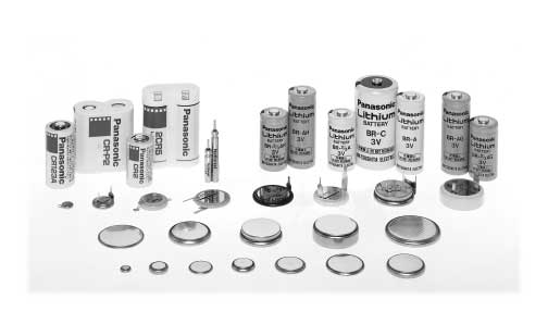

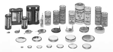
Chapter 3
Rechargeable Coin Type
Chapter 3
Vanadium Pentoxide Lithium Coin
Niobium-Lithium Coin Type
Type Batteries (VL series) . 56
Batteries (NBL series). 72
Manganese Lithium Coin Type
Manganese Titanium Lithium Coin
Batteries (ML series) . 64
Type Batteries (MT series) . 74


3-1 Vanadium Pentoxide Lithium Coin Type Batteries (VL series)
Vanadium Pentoxide Lithium Rechargeable Batteries (VL series)
These completely new coin-type lithium batteries feature vanadium oxide for the positive pole, lithium alloy for the
negative pole and a non-aqueous solvent for the electrolyte.
Chapter 3
Vanadium Pentoxide Lithium Coin Type Batteries (VL series)
Memory backup power supplies for offi ce automation equipment (personal computers, fax
audio-video equipment (VTRs, etc.), communications equipment (mobile phones, etc.), etc.
Hybrid systems with solar batteries (solar remote con-
General Specifi cations
Electrical characteristics (20°C) Dimensions (mm)
Model No.
Weight (g) JIS IEC
Nominal voltage (V) *Nominal capacity (mAh) Continuous drain (mA) Diameter Height
VL621 3 1.5 0.01 6.8 2.1 0.3 - -
VL1216 3 5.0 0.03 12.5 1.6 0.7 - -
VL1220 3 7.0 0.03 12.5 2.0 0.8 - -
VL2020 3 20.0 0.07 20.0 2.0 2.2 - -
VL2320 3 30.0 0.10 23.0 2.0 2.8 - -
VL2330 3 50.0 0.10 23.0 3.0 3.7 - -
VL3032 3 100.0 0.20 30.0 3.2 6.3 - -
* Nominal capacity shown above is based on standard drain and cut off voltage down to 2.5V at 20°C.
Chapter 3- 56

■ Charging circuits
Charging/discharging cycle
Approx. 1,000 times at 10% discharge depth to nominal capacity
Charging system*
Constant-voltage charging.(Please strictly adhere to the specifi ed charge voltage)
Operating temperature
* Consult with Panasonic concerning constant-current charging systems.
The charging circuit is crucial in terms of ensuring that full justice will be done to the battery characteristics.
Consider it carefully as the wrong charging circuit can cause trouble.
■ Precautions regarding the charge voltage setting
Under no circumstances should trickle charging, which is used for nickel-cadmium batteries, be used. Ignoring
this precaution will cause the battery voltage to rise to about 5V, resulting in a deterioration of performance.
Chapter 3
■ Charge voltage range
If a fi xed-charging method is applied, please adhere to the specifi ed charging voltage.
The guaranteed value over an operating temperature range from -20 to +60°C is 3.4V ± 0.15V.
(Actual value: 3.4V ± 0.20V)
Vanadium Pentoxide Lithium Coin Type Batteries (VL series)
* If the charging voltage exceeds the specifi cations, the internal resistance of the battery will rise and may
cause battery deterioration. Also,with a charge voltage around 4V, corrosion of the (+) terminal (case) may
occur, causing leakage. ("Infl uence of the charge voltage on VL batteries" in Chapter 3-59.)
* It is not possible for the battery capacity to recover completely when the charging voltage is below the
■ Recommended charging circuits
Basic conditions
Charge voltage: 3.4V±0.15V
Charge current: For a battery voltage of 3V
VL621 Approx. 0.2 mA or below
VL1216, VL1220 Approx. 0.5 mA or below
VL2020 Approx. 1.5 mA or below
VL2320, VL2330 Approx. 2.0 mA or below
VL3032 Approx. 4.0 mA or below
(It is permissible for the current to increase beyond the above level when the battery voltage drops below 3V.)
■ Mixed usage of batteries
Do not use these batteries and lithium primary batteries or other rechargeable batteries together, and do
not use new batteries and old batteries together even if they are of the same type.
Chapter 3- 57

Reference: Examples of 5-V charging circuits
Standard circuits
For D2 , select a diode of small inverse current(IR=1 A below / 5V)
D1, D2 : MA716(Diode type code)
D3 : MA704, MA700
Simple economical circuits
D : MA700 (Very small inverse current)
Load with 5V applied
Chapter 3
Common to all types
For D , select a diode of small inverse current (IR=1 A below / 5V)
Vanadium Pentoxide Lithium Coin Type Batteries (VL series)
For minimizing current leakage due to resistance, etc., as when charging by another battery.
For details, refer to the constant voltage element specifications
D : MA700 or MA704
✽ D : MA700 or MA704
✽ Patent pending
Select a diode having an inverse current as small as possible. (IR=1 A below / 5V)
Transistor control(for VL2320)
Chapter 3- 58
Charging characteristics
4 Common to VL621 and VL1216 / Common to VL1220 VL2020 and VL2330 Temp. 20°C
Infl uence of the charge voltage on VL batteries
If the charge voltage goes beyond its adequate range, battery performance may deteriorate early. Be sure to observe the guaranteed
Chapter 3
charge voltage.
Prohibited operating range
Early battery deterioration region
60˚C withstand voltage limit
Vanadium Pentoxide Lithium Coin Type Batteries (VL series)
Adequate charge voltage range
Operational range
(guaranteed specified value)
The lower the charging voltage becomes,the less the capacity becomes.
Chapter 3- 59
■ Dimensions(mm)
■ Dimensions(mm)
■ Specifi cation
■ Specifi cation
Chapter 3
■ Discharge Temperature Characteristics
■ Discharge Temperature Characteristics
Vanadium Pentoxide Lithium Coin Type Batteries (VL series)
■ Consumption current vs. Duration time
■ Consumption current vs. Duration time
Chapter 3- 60
■ Dimensions(mm)
■ Dimensions(mm)
■ Specifi cation
■ Specifi cation
Chapter 3
■ Discharge Temperature Characteristics
■ Discharge Temperature Characteristics
Vanadium Pentoxide Lithium Coin Type Batteries (VL series)
■ Consumption current vs. Duration time
■ Consumption current vs. Duration time
Chapter 3- 61
■ Dimensions(mm)
■ Dimensions(mm)
■ Specifi cation
■ Specifi cation
Chapter 3
■ Discharge Temperature Characteristics
■ Discharge Temperature Characteristics
Vanadium Pentoxide Lithium Coin Type Batteries (VL series)
■ Consumption current vs. Duration time
■ Consumption current vs. Duration time
Chapter 3- 62
■ Dimensions(mm)
■ Specifi cation
Chapter 3
■ Discharge Temperature Characteristics
Vanadium Pentoxide Lithium Coin Type Batteries (VL series)
■ Consumption current vs. Duration time
Chapter 3- 63
3-2 Manganese Lithium Coin Type Batteries (ML series)
Manganese Lithium Rechargeable Batteries (ML series)
These super compact lithium rechargeable batteries feature a manganese compound oxide for the
positive electrode, a lithium/aluminum alloy for the negative electrode and a special non-aqueous
Chapter 3
solvent for the electrolyte. They can easily be incorporated into circuits where 3V ICs are used
to save space.
Memory backup power supplies for mobile phones, memory
cards, pagers and other compact communications equipment,
data terminals and offi ce automation equipment
Manganese Lithium Coin Type Batteries (ML series)
General Specifi cations
Electrical characteristics (20°C) Dimensions(mm)
Model No.
Weight(g) JIS IEC
Nominal voltage(V) *Nominal capacity(mAh) Continuous drain(mA) Diameter Height
ML612S 3 2.6 0.01 6.8 1.2 0.15 - -
ML614S 3 3.4 0.01 6.8 1.4 0.17 - -
ML616S 3 2.9 0.01 6.8 1.6 0.2 - -
ML621S 3 5.0 0.01 6.8 2.1 0.3 - -
ML920S 3 11.0 0.03 9.5 2.0 0.5
ML1220 3 17.0 0.03 12.5 2.0 0.8
ML2020 3 45.0 0.10 20.0 2.0 2.2 - -
ML2430(Under development) 3 120.0 0.30 24.5 3.0 4.0
*Nominal capacity shown above is based on standard drain and cut off voltagedown to 2.0V at 20°C.
Chapter 3- 64
■ Charging circuits
Charging/discharging cycle
Approx. 1,000 times at 10% discharge depth to nominal capacity
Charging system*
Constant-voltage charging.(Please strictly adhere to the specifi ed charge voltage)
Operating temperature
* Consult with Panasonic concerning constant-current charging systems.
The charging circuit is crucial in terms of ensuring that full justice will be done to the battery characteristics.
Consider it carefully as the wrong charging circuit can cause trouble.
■ Precautions regarding the charge voltage setting
Under no circumstances should trickle charging, which is used for nickel-cadmium batteries, be used.
Ignoring this precaution will cause the battery voltage to rise to about 5V, resulting in a deterioration of performance.
Chapter 3
■ Charge voltage range
If a fi xed-charging method is applied, please adhere to the specifi ed charging voltage.
Guaranteed voltage is 2.8V 3.2V at the temperature of -20°C 60°C.
Manganese Lithium Coin Type Batteries (ML series)
* If the charging voltage exceeds the specifi cations, the internal resistance of the battery will rise and may cause
battery deterioration. Also, with a charge voltage around 4V, corrosion of the (+)terminal (case) may occur,
causing leakage. ("Infl uence of the charge voltage on ML batteries" on the back.)
* It is not possible for the battery capacity to recover completely when the charging voltage is below
the specifi cation.
■ Recommended charging circuits
Basic conditions
Fixed-voltage charge
Charge voltage: 2.8 3.2V (Standard voltage: 3.1V)
Charge current: For a battery voltage of 2.5V
ML612S,ML614S,ML616S Approx. 0.3 mA or below
ML621S Approx. 0.6 mA or below
ML920S Approx. 1.2 mA or below
ML1220 Approx. 1.2 mA or below
ML2020 Approx. 3.0 mA or below
■ Mixed usage of batteries
Do not use these batteries and lithium primary batteries or other rechargeable batteries together, and do
not use new batteries and old batteries together even if they are of the same type.
Chapter 3- 65
Reference: Examples of 5-V charging circuits
When charging using another battery
ML612S, ML614S, ML616S
3.0V(3V or more)
Standard circuits
For D2 , select a diode of small inverse current
D1, D2 : MA716(Diode type code)
D3 : MA704, MA700
Simple economical circuits
D : MA700 : Very small inverse current
Chapter 3
* VF of D will be different from the value given above if a current in excess of 100 A flows to
the load during operation. Compensation must be provided by the resistors in such cases.
Manganese Lithium Coin Type Batteries (ML series)
Infl uence of the charge voltage on ML batteries
If the charge voltage goes beyond its adequate range, battery performance may deteriorate early. Be sure to observe the guaranteed charge voltage.
Prohibited operating range
Early battery deterioration region
60 C withstand voltage limit
Adequate charge voltage range
Operational range
(guaranteed specified value)
The lower charging voltage becomes,
the less capacity becomes.
Chapter 3- 66
■ Dimensions(mm)
■ Dimensions(mm)
■ Specifi cation
■ Specifi cation
Chapter 3
■ Discharge characteristics
■ Discharge characteristics
Manganese Lithium Coin Type Batteries (ML series)
■ Consumption current vs. Duration time
■ Consumption current vs. Duration time
Chapter 3- 67
■ Dimensions(mm)
Lithium Battery Holders for ML616S
These battery holders are designed for sure and easy
loading/removal of Panasonic coin type lithium batteries
in/from equipment enabling the batteries to fully exploit their
capabilities as the backup power supply in C-MOS RAM
memory and microcomputer memory. All of the battery holders
are designed to prevent inverted insertion of the battery.
Chapter 3
■ Discharge characteristics
Manganese Lithium Coin Type Batteries (ML series)
■ Precaution for washing battery holders
The battery holders can be adversely affected by some
detergents used in the circuit board washing process and
may result in cracks forming in the holder. Please test the
■ Consumption current vs. Duration time
holders in your washing process before use.
Chapter 3- 68
■ Dimensions (mm)
■ Dimensions (mm)
■ Specifi cation
■ Specifi cation
Chapter 3
■ Discharge characteristics
■ Discharge characteristics
Manganese Lithium Coin Type Batteries (ML series)
■ Charge / discharge characteristics
■ Consumption current vs. Duration time
■ Consumption current vs. Duration time
Chapter 3- 69
■ Dimensions(mm)
■ Dimensions(mm)
■ Specifi cation
■ Specifi cation
Chapter 3
■ Discharge characteristics
■ Discharge characteristics
Manganese Lithium Coin Type Batteries (ML series)
Consumption current vs. Duration time
Consumption current vs. Duration time
Chapter 3- 70
■ Dimensions(mm)
Under development
■ Specifi cation
Chapter 3
■ Discharge characteristics
Manganese Lithium Coin Type Batteries (ML series)
■ Consumption current vs. Duration time
Chapter 3- 71
3-3 Niobium-Lithium Coin Type Batteries (NBL series)
Niobium-Lithium Rechargeable Batteries (NBL series)
The NBL series eliminates the need for a voltage boosting circuit since they can be charged at a low
voltage. They help to simplify charging circuits.
Chapter 3
Memory backup power supplies for mobile phones
using ICs which reduce the voltage to lower levels
and which are driven at 2.5V or so.
General Specifi cations
Niobium Lithium Coin Type Batteries (NBL series)
Electrical characteristics (20°C) Dimensions(mm)
Model No.
Weight(g) JIS IEC
Nominal voltage(V) *Nominal capacity(mAh) Continuous drain(mA) Diameter Height
NBL621 2 4 0.01 6.8 2.1 0.25 - -
*Nominal capacity shown above is based on standard drain and cut off voltage down to 1.0V at 20°C.
Consult Panasonic for charging conditions.
Chapter 3- 72
■ Dimensions(mm)
■ Specifi cation
Chapter 3
■ Discharge characteristics
Niobium Lithium Coin Type Batteries (NBL series)
■ Recovered capacity (According to charge voltage)
Chapter 3- 73
3-4 Manganese Titanium Lithium Coin Type Batteries (MT series)
Manganese Titanium Lithium Rechargeable Batteries (MT series)
These coin-type manganese titanium lithium coin batteries use a lithium-manganese complex oxide
for the positive pole and a special lithium-titanium complex oxide for the negative pole. They provide a
Chapter 3
capacity which is more than 10 times that of capacitors of the same size.
Main power supplies in compact products such as
rechargeable watches
Memory backup power supply for pagers, timers, etc.
Manganese Titanium Lithium Coin Type Batteries (MT series)
General Specifi cations
Electrical characteristics (20°C) Dimensions(mm)
Model No.
Weight(g) JIS IEC
Nominal voltage(V) *Nominal capacity(mAh) Continuous drain(mA) Diameter Height
MT516 1.5 0.9 0.05 5.8 1.6 0.15 - -
MT616 1.5 1.05 0.05 6.8 1.6 0.20 - -
MT621 1.5 2.5 0.05 6.8 2.1 0.25 - -
MT920 1.5 4.0 0.10 9.5 2.0 0.45 - -
MT1620 1.5 11.0 0.50 16.0 2.0 1.25 - -
*Nominal capacity shown above is based on standard drain and cut off voltage down to 1.0V at 20°C.
Consult Panasonic for charging conditions.
Chapter 3- 74
■ Dimensions (mm)
■ Dimensions (mm)
■ Specifi cation
■ Specifi cation
Chapter 3
■ Charge / discharge characteristics
■ Charge / discharge characteristics
Manganese Titanium Lithium Coin Type Batteries (MT series)
■ Consumption current vs. Duration time
■ Consumption current vs. Duration time
Chapter 3- 75
■ Dimensions (mm)
■ Dimensions (mm)
■ Specifi cation
■ Specifi cation
Chapter 3
■ Charge / discharge characteristics
■ Charge / discharge characteristics
Manganese Titanium Lithium Coin Type Batteries (MT series)
■ Consumption current vs. Duration time
■ Consumption current vs. Duration time
■ Discharge characteristics
Chapter 3- 76
■ Dimensions (mm)
■ Specifi cation
Chapter 3
■ Charge / discharge characteristics
Manganese Titanium Lithium Coin Type Batteries (MT series)
■ Consumption current vs. Duration time
Chapter 3- 77
Chapter 4
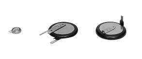
Batteries with Terminals and
Soldering Lithium Batteries
Chapter 4
Batteries with Terminals. 80
Soldering. 80
Batteries with Terminals
of applications, obviating eliminating the need for
Highly Reliable Terminal Welding
reinforcement or other such means.
(1) Using a laser to weld terminals
(2) Execution of pre-soldering
Panasonic uses a laser welding method to weld the
The tips of the terminals are pre-soldered in order to
terminals onto the batteries so they can be mounted
enhance the reliability of the soldering.
onto PC boards by soldering. This method has the
effect of boosting the tensile strength accompanying a
welding strength to approximately 100N (approx.10kgf)
compared with 20N to 50N (approx. 2 to 5 kgf) yielded
by the conventional resistance welding method. The
method also more or less cuts in half the individual
variations occurring in the welding. Furthermore, it
Panasonic offers a full range of batteries with terminals
enables terminals to be welded onto thin batteries, such
for PCB mounting. Since the terminals come in a variety
as those with a thickness of 1.6 mm, and it improves
of types, please contact Panasonic for further details.
compatibility with many other uses. This highly reliable
A more limited selection of simple battery holders to
terminal soldering method can be used in a wide range
support the batteries is also available.
(1) Using a soldering iron
Do not allow the soldering iron to make direct contact
with the bodies of the batteries. Proceed with the
Example where the terminals were soldered straight onto a
soldering quickly within 5 seconds while maintaining the
coin-type lithium battery, the terminals were connected to
Chapter 4
a PC board or other electronic components, and the heat
iron tip temperature at about 350°C, and do not allow the
generated by the soldering adversely affected the battery, resulting in a deterioration of the battery characteristics:
temperature of the battery bodies to exceed 85°C.
The heat generated when terminals are mounted using solder
(2) Automatic dip-soldering bath
causes lithium to melt.
Soldering with a dip-soldering bath can be used but
do not allow the temperature of the battery bodies to
The separator melts and becomes perforated.
exceed 85°C. It is important to note, depending on the
temperature conditions inside the dipping device,that
The positive and negative poles are welded together,
the battery body temperature may rise after dipping
causing "internal shorting."
due to the residual heat retained. When a post-dipping
Batteries with Terminals and Soldering
temperature rise is observed, review the temperature
In terms of the battery characteristics, the open-circuit voltage
conditions and consider a dipping time reduction or a
and electrical capacity are both reduced.
way of forcibly cooling the batteries after dipping.
The battery loses its functions or it bursts in rare cases.
Dip-soldering bath temperature
Within 5 sec.
* Consult Panasonic if the battery body temperature will exceed 85°C.
Never Use Refl ow Soldering
Separator(note 2)
Never use reflow soldering since doing so directly
heats the battery surface to high temperatures,
causing electrolyte leakage, deterioration of battery
characteristics and risking bursting or ignition.
(note 1)Metal whose melting point is about 180°C(note 2)Non woven cloth of polypropylene whose melting point is about 165°C
Chapter 4- 80
Chapter 5
Standards and Regulations
QS9000 / ISO9001 Approval . 82
Security Export Control . 83
Transporting Lithium Batteries. 83
Chapter 5
QS9000 / ISO9001 Approval
The Lithium & Micro Battery Division has acquired
certifi cation under ISO9001, the international standard
The QS-9000 standard was established by the "Big
for quality assurance, for its cylindrical type lithium
Three" U.S. automakers (Daimler-Chrysler, Ford
batteries and coin-type lithium batteries.
and GM) on the basis of the ISO9001 international
In addition, we have acquired certification under
standard governing quality assurance but with additional
QS-9000, the quality standard for the automobile
requirements of their own.
manufacturing industry, for its coin-type lithium primary
A company which has been certifi ed under this standard
can supply highly reliable products by incorporating
into its quality system proven "predictive management"
techniques which are substantiated by numerical data
from a customer satisfaction survey, failure mode and
effects analysis (FMEA), process capability analysis,
measurement systems analysis, etc. which are required
under the standard.
Standards and Regulations
Chapter 5
Chapter 5- 82
Transporting Lithium Batteries
■ Regulations for transporting lithium batteries (only batteries which have a solid cathode electrode are listed)
(as of March / 2000)
Name of regulations
ICAO IATA
Means of transportation
air cargo
Total weight of
1g or less
1g or less
1g or less
1g or less
Total weight of
2g or less
2g or less
2g or less
2g or less
lithium battery pack
Total weight of
5g or less
5g or less
5g or less
5g or less
Total weight of
25g or less
25g or less
25g or less
25g or less
lithium battery pack
Total weight of
12g or less
12g or less
12g or less
12g or less
Total weight of
500g or less
500g or less
500g or less
500g or less
lithium battery pack
Total weight of
500g or less
500g or less
500g or less
500g or less
Up to 5kg of batteries can be Up to 35kg of batteries can be Up to 250kg of batteries can be DOT;49CFR173.185
carried if they are packed in a carried if they are packed in a carried if they are packed in a
container which is approved 2nd container which is approved
container which is approved 2nd
class by UN.
2nd class by UN.
class by UN.
A: The batteries listed above are not subject to these restrictions provided that they satisfy the A45 conditions,IATA.
B: The batteries listed above are not subject to these restrictions provided that they have been certifi ed as
satisfying the test standards specifi ed in the U.N. recommendation and as not falling under the classifi cation
Standards and Regulations
of hazardous items.
C: The batteries listed above can be transported provided that they satisfy the conditions stipulated by the laws and
regulations listed below and that they meet the packaging standards.
The regulation above is an extract of the latest version. See the original for details.
U
(International Civil Aviation Organization)
(International Air Transport Association)
(International Marin Organization)
(Department Of Transportation)
This section of the catalog is quoted by transportation hazards issued by the organizations shown above.
Chapter 5
Security Export Control
"Security export control" entails observing the legislation
Lithium batteries are on the list of items subject to the
provided to maintain international peace and safety
Export and Trade Control Regulation (Item 7 in annex
by preventing the proliferation of weapons of mass
Table 1) but all the products mentioned in this catalog
destructions (nuclear weapons, chemical warfare
are exempt from these regulations.
weapons, biological weapons and missiles) and the
The above notwithstanding, these batteries may be
excessive buildup of conventional weapons. COCOM,
subject to the regulations depending on their ultimate
the committee that imposed controls on exports to
destination, application and other conditions.
the Communist bloc, was disbanded on March 31,
When a non-exemption/exemption certifi cate is required
1994. However, the items, etc. which were restricted
for exportation, etc. or if you have any queries, contact
by COCOM are still the target of the restrictions but
a Panasonic sales representative.
they are now also subject to some amendments which
were made in September 1996.
Chapter 5- 83
Chapter 6
Avoiding Hazards and
Preventing Quality Problems
Avoiding Hazards . 86
Preventing Quality Problems . 87
Chapter 6
Case Study and Explanation
To store batteries, place each of the batteries in the sections provided on the designated tray in such a way that
they will not make contact with one another.
2,000 new batteries were taken out from the 20-piece
21 cylindrical type lithium batteries with tab terminals
tray containers and thrown randomly into a cardboard
were placed in a 20 piece tray--one battery more
box where they were stacked on top of one another.
than the capacity of the 20-piece tray shown in the
About 30 minutes later, smoke was seen emanating
fi gure--two of the batteries were placed together with
from the batteries followed by ignition several minutes
their poles reversed. As a result, the tab terminals
came into contact with each other, causing external
Case study: Ignition of batteries stacked together
shorting, and the temperature of the two batteries rose
dramatically, generating heat and causing the halon
tubes to burst.
Since two batteries were placed in a space (indicated
by ) allocated to one battery, their terminals made
ing resulted.
Avoiding Hazards and Preventing Quality Problems
This particular case involves batteries which were
packed in trays and destined for OEMs. The batteries
were packed in an intermediate package consisting of
10 trays with each tray containing 20 (or 40) batteries,
and the trays were stacked on top of each other. The
intermediate package (of the 10 trays) was opened
at the distribution stage of our operations, and fi ve
of the trays were delivered to one customer. Since
the trays were stored at an angle inside the box, the
batteries fell out of their
positions on the trays
and became stacked
up on the bottom inside
the small box. As a
Generating heat and deterioration of capacity
result, some of the
batteries burst.
To store batteries, place each of the batteries in
the sections provided on the designated tray in
Case study: Bursting
such a way that they will not make contact with
Chapter 6
of batteries stacked on
one another.
top of one another
Chapter 6- 86
Preventing Quality Problems
Reduction of Battery Voltage and Deterioration of Capacity
(1) Reduction of battery voltage and deterioration of capacity through contact with
antistatic conductive materials
Incidents have been reported where terminal-mounted batteries for memory backup or coin-type lithium batteries
have come into contact with antistatic conductive materials, thus forming external discharge circuits and leading
to voltage drops or capacity deterioration.
In manufacturing plants using ICs, LSI and other semiconductor components, thoroughgoing antistatic measures
are taken. Various protective materials are used to prevent static: most of them have special compounds of carbon,
aluminum foil and other metals and are therefore conductive. These protective materials are used, for example, in the
form of packaging bags, trays, mats, sheets, fi lms, corrugated boards and resin cases.
A protective material may have a resistance ranging from 103 to 106 Ω/cm, for instance. This means that if the (+) and (-) terminals of a battery come into contact with this material, a current ranging from several milliamperes to several
microamperes will fl ow and the battery will discharge, causing voltage drop and capacity deterioration.
A terminal-mounted battery was inserted into a
A battery was placed directly
Exclusive grounding line
on a rubber sheet spread over
conductive mat. The battery charge was exhausted
a worktable. The (+) and (-)
in several days.
terminals were in contact with
charge was exhausted.
Conductive rubber sheet
Avoiding Hazards and Preventing Quality Problems
Battery-mounted PC boards were inadvertently
When batteries are to be used near protective materials,
brought into contact with spacers and a conductive
take every possible care to ensure that the (+) and (-)
rubber sheet. The battery
terminals of the batteries or PC boards, etc. on which
charge was exhausted.
batteries are mounted do not touch these protective
materials directly.
A battery-mounted PC board was inadvertently brought into contact with a conductive resin case. The battery charge was exhausted.
Conductive resin case
Chapter 6
Chapter 6- 87
Preventing Quality Problems
(2) Reduction of battery voltage and deterioration of capacity through contact between batteries
Incidents have been reported where terminal-mounted batteries for memory backup or coin-type lithium batteries
have come into contact each other, thus forming discharge circuits (shorted state) and leading to voltage drops or
capacity deterioration. Observe the following precautions.
1. Remove the batteries from the tray one at a time.
If the tray is turned upside down, the batteries will come into contact with each other, forming discharge circuits.
2. Do not place batteries randomly in a parts box or other container.
Discharge circuits will be formed by multiple batteries coming into contact numbers of the batteries, causing the
batteries to discharge and drain.
Recommended procedures
Prohibited procedures
*Utilize the tray lid in taking out batteries
*Do not throw batteries randomly into a parts box by turning over trays containing batteries.
Intermediate package(200 batteries):20 pieces ✕ 10 trays
Tray containing batteries
Trays containing batteries
Lid tray (tray with no hole)
Avoiding Hazards and Preventing Quality Problems
Discharge circuits
Trays containing batteries
Batteries being exhausted
Battery being exhausted
Battery being exhausted
*Contact of batteries with each other forms discharge circuits, thus the batteries are drained.
*Lay a tray lid flat and place a tray containing batteries on top of it: batteries are pushed up by protrusions of the lid tray so that they can be easily picked up with fingers.
Chapter 6
Chapter 6- 88
Preventing Quality Problems
Memory Erasure Problems
<Reference Sample>
Coin-type lithium batteries are often used as the power
supplies for memory backup in various equipment.
However problems with the erasure of valuable data
in the memory due to improper contact between the
batteries and equipment have been reported.
1. When batteries are to be used continuously for
a prolonged period.
Select tab terminal-mounted batteries, and solder
the tabs to the battery connection terminals of the
equipment. (See Fig. 1)
When batteries need to be replaced, use a
battery holder (see Fig. 2) or battery with lead wire
connectors (see Fig. 3). Battery holders made
by Panasonic (exclusively for the CR2032 and
BR2032, see Fig. 2) are available for use.
2. When batteries need to be replaced in the short
term, select batteries with no terminals or lead
wire connectors.
Use of Y-shaped terminals (2-point contact) for
both the (+) and (-) poles as the shape of the
connection terminals in the equipment helps to
Avoiding Hazards and Preventing Quality Problems
achieve a more stable contact. (See Fig. 4)
The contact pressure of the contacts should be
no less than 2 to 10N (approx. 200 to 1000 gf).
To prevent momentary contact failure of several
milliseconds in the circuit, the use of a tantalum
capacitor, etc. with a capacitance of several
microfarads is effective. (See Fig. 6)
For the connection terminals of the equipment,
Fig. 5: excessive load
use iron or stainless steel with nickel plating at the
very least. Gold-plating is more suitable when the
contact resistance must be reduced.
Note: Do not touch batteries with bare hands because
perspiration (salt), body oil etc. will increase the
surface resistance which may lead to defective
Chapter 6
Chapter 6- 89
Batteries - Create A New World
For Literature and General Product Information:
Panasonic Industrial Europe GmbH
Panasonic Industrial Europe GmbH
Avda. Josep Tarradellas, 20-30, 5°
Bracknell Berkshire
08029 Barcelona - Spain
Tel: +34 93-494 92 42
Fax: +34 93-419 89 31
Tel: +44 1344-853262Fax: +44 1344-853724
Panasonic Industrial Europe GmbH
Panasonic Industrial Europe GmbH
270 avenue du Président Wilson
93218 Saint Denis La Plaine
Tel: +39 02-6788-232
Tel: +33 1-49 46 44 10
Fax: +39 02-6788-207
Fax: +33 1-49 46 42 20
Germany (all other european countries)
Panasonic Industrial Europe GmbH
Winsbergring 15
22525 Hamburg
Tel: +49 40-85 386-157
Fax: +49 40-85 386-160
For more details, please contact:
Panasonic is a registered trademark of Matsushita Electric Co., Ltd.
P 2002. Printed in Germany. This catalogue has been produced using un-chlorinated paper.
Source: http://assets.kreativbox24.de/534ffda3e74787059d000002/pdfs/lithium-2-vl.pdf
GENERICOS CENTROAMERICANOS, S.A. AÑO IX No. 68 Actualidad MédicaEspecial para Folia Médica: Dr Carlos FernándezEsteroides en el tratamiento inicial de la SepsisEl dolor lumbar: Dr E. J. MerladetFibra y cáncer colorrectalOzonoterapia¿Cuándo mata la enfermedad coronaria?más.
MILITARY MEDICINE, 177, 9:1015, 2012 Healing Touch With Guided Imagery for PTSD in Returning Active Duty Military: A Randomized Controlled Trial Shamini Jain, PhD*†; CDR George F. McMahon, NC USN‡; LCDR Patricia Hasen, NC USN‡; CDR Madelyn P. Kozub, NC USN‡; Valencia Porter, MD, MPH∥; Rauni King, RN, MIH, CHTP§; Erminia M. Guarneri, MD§ ABSTRACT Post-traumatic stress disorder (PTSD) remains a significant problem in returning military and warrantsswift and effective treatment. We conducted a randomized controlled trial to determine whether a complementarymedicine intervention (Healing Touch with Guided Imagery [HT+GI]) reduced PTSD symptoms as compared totreatment as usual (TAU) returning combat-exposed active duty military with significant PTSD symptoms. Active dutymilitary (n = 123) were randomized to 6 sessions (within 3 weeks) of HT+GI vs. TAU. The primary outcome was PTSDsymptoms; secondary outcomes were depression, quality of life, and hostility. Repeated measures analysis of covariancewith intent-to-treat analyses revealed statistically and clinically significant reduction in PTSD symptoms ( p < 0.0005,Cohen's d = 0.85) as well as depression ( p < 0.0005, Cohen's d = 0.70) for HT+GI vs. TAU. HT+GI also showedsignificant improvements in mental quality of life ( p = 0.002, Cohen's d = 0.58) and cynicism ( p = 0.001, Cohen's d =0.49) vs. TAU. Participation in a complementary medicine intervention resulted in a clinically significant reductionin PTSD and related symptoms in a returning, combat-exposed active duty military population. Further investigation ofGT and biofield therapy approaches for mitigating PTSD in military populations is warranted.


