Mpie.de

M.I. Muglali, A. Erbe, Y. Chen, C. Barth, P. Koelsch, M. Rohwerder: Electrochimica Acta, 90, 17-
26 (2013).
Final copy-edited version of the manuscript is available from: Modulation of electrochemical hydrogen evolution rate by araliphatic thiol monolayers on gold Mutlu I. Muglalia, Andreas Erbea,∗, Ying Chena,b, Christoph Barthc, Patrick Koelschc,d, Michael Rohwerdera,1,∗∗ a Max-Planck-Institut f¨ur Eisenforschung GmbH, Department of Interface Chemistry and Surface Engineering, Max-Planck-Str. 1, 40237 D¨ b Center for Electrochemical Sciences, Ruhr-Universit¨at Bochum, Universit¨atstr. 150, 44780 Bochum, Germany c Institute of Toxicology and Genetics, Karlsruhe Institute of Technology, Postfach 3640, 76021 Karlsruhe, Germany d National ESCA and Surface Analysis Center for Biomedical Problems, Department of Bioengineering, University of Washington, Box 35170, Seattle, Washington 98195-1750, Electroreductive desorption of a highly ordered self-assembled monolayer (SAM) formed by the araliphatic thiol (4-(4-(4-pyridyl)phenyl)phenyl)meth- anethiol leads to a concurrent rapid hydrogen evolution reaction (HER).
The desorption process and resulting interfacial structure were investigated by voltammetric techniques, in situ spectroscopic ellipsometry, and in situ vibrational sum–frequency–generation (SFG) spectroscopy. Voltammetric experiments on SAM-modified electrodes exhibit extraordinarily high peak currents, which differ between Au(111) and polycrystalline Au substrates.
Association of reductive desorption with HER is shown to be the origin of ∗Corresponding author; Phone: +49 211 6792 890, Fax: +49 211 6792 218 ∗∗Corresponding author; Phone: +49 211 6792 914, Fax: +49 211 6792 218 Email addresses: [email protected], [email protected] (Andreas Erbe), [email protected] (Michael Rohwerder) 1 ISE member.
Preprint submitted to Electrochimica Acta November 24, 2012 the observed excess cathodic charges. The studied SAM preserves its two– dimensional order near Au surface throughout a fast voltammetric scan even when the vertex potential is set several hundred millivolt beyond the des- orption potential. A model is developed for the explanation of the observed rapid HER involving ordering and pre–orientation of water present in the nanometer–sized reaction volume between desorbed SAM and the Au elec- trode, by the structurally extremely stable monolayer, leading to the observed catalysis of the HER.
Keywords: Reductive SAM desorption; Hydrogen evolution; Catalysis; Sum frequency generation spectroscopy; Spectroscopic ellipsometry Self-assembled monolayers (SAMs) are often employed for electrochem- ical applications such as control of charge transfer [1, 2], production of (bio)electrochemical sensors [3–5], metal/organic/metal junctions [6–8], and barrier layers against metal corrosion [9–11]. It is essential to understand the effect of SAM–modified electrodes on electron transfer reactions, as well as their interfacial structure under electrochemical conditions for their ultimate use in electrolytic media.
In most cases, the rate of an interfacial chemical reaction is reduced by the presence of adsorbates because of their blocking of active sites on the surface, as has been shown, e.g., for the oxygen reduction reaction (ORR) on Au(111) [9, 12, 13]. If the adsorbate blocks the active sites through covalent bonds, such a rate decrease is also expected for the HER. On the other hand, redox-active physisorbed monolayers have been shown to act as catalysts towards the HER [14].
For thiol self-assembled monolayers (SAMs) on Au, HER occurs in an electrode potential range beyond reductive desorption of the SAMs [15], leading to a complex interplay between different interfacial reactions. To understand this complex interplay, it is essential to understand the interfa- cial properties of SAM-modified electrodes under electrochemical conditions.
In this context, the influence of the electrode potential on formation kinetics [16, 17], structural properties [18–20], and ionic permeability of SAMs has been subject to several works [19, 21]. Especially electrochemical desorp- tion/readsorption studies revealed important details concerning the nature of the interfacial interactions between a chemisorbed monolayer and a metallic substrate, besides defining the applicable potential range for SAM-modified On the cathodic side, this potential range is typically limited by the re- ductive desorption of thiol-SAMs from the Au substrate, which is commonly described by the simple reaction [22] RSAu + e– −→ RS– + Au Although the cleavage of the Au-S covalent bond has been established, many aspects of the entire electroreductive desorption mechanism of thiol mono- layers are unclear and have been subject of a number of studies, in most cases excluding the effect on and the role of the HER [23–37]. Besides the currents originating from the Faradaic 1, incidental capacitive currents have been reported during desorption of a SAM as a consequence of the transition between a SAM–covered and a bare interface. Cathodic peaks originating from capacitive currents are usually not larger than 20-30 % of the des- orption currents, as reported for long-chain aliphatic thiols [23–25, 32–36], because charges transferred during such capacitive processes are smaller than the charges transferred during Faradaic reactions.
The state of the molecular units of SAMs during and after electrore- ductive desorption is decisive for the electrode's activity towards interfacial reactions, including HER. After electroreductive cleavage of the S-Au bonds, soluble molecules diffuse into the electrolyte, while long-chain alkanethio- lates reside in the double layer region as a consequence of their poor water solubility.[38] Within the double layer, chemically desorbed long-chain alka- nethiolates form aggregates, as concluded from spectroscopic and microscopic studies [26, 28, 30, 31]. Depletion of these aggregates has been proposed as the source of additional capacitive currents, which are usually observed as a separate peak in voltammograms during desorption of long n-alkanethiols.
This hypothesis was later disproven by a second-harmonic-generation study [37]. In addition, vibrational sum-frequency-generation (SFG) spectroscopy has been applied to investigate molecular ordering and orientation within self-assembled monolayers at electrified interfaces [39–42], and ex situ af- ter treatment at different potentials [38]. The majority of previous studies of electroreductive desorption focused on commonly used aliphatic SAMs.
In recent years, interest has shifted towards SAMs consisting of aromatic molecular units, due to their enhanced stability and interesting electric and electronic properties [1, 2, 43–45]. So far, to the author's knowledge, no de- tailed desorption study of such technologically promising SAMs composed of large aromatic molecules with more than two aromatic rings has been car- ried out. Different in mechanism from multiwave desorption peaks observed for n-alkanethiols, long araliphatic thiols show an extraordinary multiwave response during electroreductive desorption [46]. The corresponding trans- ferred charges are too large for a capacitive process and even larger than the Faradaic desorption reaction. The magnitude of the unknown, desorption- related Faradaic process points to involvement of the HER [46]. A full in- vestigation of the physical state of the desorbed molecules on the electrode surface requires spectroscopic or microscopy techniques combined with elec- This work examines the unusual desorption behavior of the highly ordered araliphatic thiol monolayers using previously characterized SAMs of (4-(4- (4 pyridyl)phenyl)phenyl)methanethiol (PyPP1) and 2-(4-(4-(4-pyridyl)phe- nyl)phenyl)ethanethiol (PyPP2). A series of voltammetric measurements have been performed to determine the origin of the extraordinarily large cathodic peaks that appear after reductive desorption. Transient states at the SAM-Au interface and within the monolayer film and during HER have been monitored in situ and in operando by femtosecond-based broadband SFG spectroscopy and spectroscopic ellipsometry. Combining the voltammetric and spectroscopic results, a model is proposed explaining the voltammetric response of electroreductive desorption of the investigated SAMs.
2.1. Samples PyPP1 and PyPP2 organothiols were synthesized as described elsewhere [47]. Au(111) substrates were prepared by evaporating gold onto freshly cleaved mica sheets at a substrate temperature of 450◦C in a Leybold Uni- vex 450 system. Prior to use, the Au films were annealed in a H2 flame.
Polycrystalline Au (poly-Au) substrates were mechanically polished. SAMs were formed by immersion of the Au substrates into 20 µM ethanolic thiol solutions for 12-15 h. After removal from solution, samples were thoroughly rinsed with ethanol and purged with nitrogen gas. All chemicals used were in reagent grade.
2.2. Voltammetry For all electrochemical measurements a Compactstat potentiostat (Ivium Technologies, The Netherlands) was employed. Deaerated 0.1 M NaOH so- lution was used as electrolyte. Cyclic voltammogramms (CVs) on SAM- modified Au(111) electrodes were measured with a scan rate of 50 mV s-1, unless stated otherwise. All electrode potentials E herein are referred to an Ag/AgCl (3 M KCl) reference electrode. For determination of the charges Q per electrode area transferred during a voltammetric peak, a linear baseline was set between the vertices of the peaks in the curves of the current densities j. This baseline was subsequently subtracted from the original j.
For hydrodynamic measurements a rotating disk electrode (RDE) assem- bly, and a rotating ring-disk electrode (RRDE) assembly (Pine Research Instruments, USA) were used. In both configurations, disk electrodes con- sisted of a mirror polished polycrystalline Au disk. In the RRDE tip, around the poly-Au disk (diameter 5 mm), a Pt ring was placed with 6.5 mm and 7.5 mm inner and outer diameters, respectively. Prior to measurements, both the ring and the disk electrodes were modified with a PyPP1 monolayer, so that during the measurement, thiolate adsorption on the ring was prevented.
In this way, any oxidative current detected on the ring could directly be assigned to H2 oxidation at the applied ring potential (ER = -0.5 V) but not to oxidative adsorption of thiolates. Collection efficiency of the SAM– modified Pt ring was determined to be ≈0.05 (compared to 0.43 without SAM modification).
2.3. Ellipsometry For spectroscopic ellipsometry measurements, a PyPP1/Au(111) (2 cm x 1.5 cm) sample was placed in a homemade PTFE electrochemical cell with suitable apertures for incident and reflected light, as well as for a Ag/AgCl (3 M KCl) microreference electrode and a Pt spiral as counter electrode.
The cell was placed in the beam path of a SE 800 spectroscopic ellipsometer (Sentech Instruments, Germany) [48, 49]. The ellipsometric angles Ψ and ∆ were measured every ≈5 s for wavelengths λ from 300 to 820 nm during CV measurements with a scan rate of 5 mV s-1 between 0 V and -1.6 V. The angles are transformed into the ellipsometric ratio ρ = rp = tan (Ψ) ei∆ with The ratio of the amplitude reflection coefficients rp and rs for p- and s- polarized light, respectively, was analyzed using a perturbation approach [51].
The perturbation parameter J1 is related to the transition of the dielectric function ǫs(z) of the interfacial region perpendicular to the interface in z- 1 − ǫs(z)) (ǫs(z) − ǫ2) For layer and layer systems with a total thickness small compared to the λ, ρ is expanded to first order around a step profile in the dielectric function with ρ0, yielding [51] ǫ21ǫ2(q1/ǫ1 + q2/ǫ2)2 is the wavevector component parallel to the interface at which a plane wave impinges under an angle of θ1, while is the wavevector component perpendicular to the interface in the respective medium, where index 1 indicates the medium of incidence and 2 indicates the gold substrate. Literature values have been used for the wavelength- dependence of the dielectric functions ǫ1 and ǫ2 of the electrolyte [52], and gold substrate [53, 54], respectively. Eq. 2 can be solved for J1 and used for a computation of J1 from experimental data.
For measurements of ρ0, E of a bare Au electrode in 0.1 M NaOH was varied between 0 and -0.5 V. In this range, recorded changes were on the order of the noise level.
2.4. Sum–Frequency–Generation Spectroscopy (SFG) The SFG measurements were performed on a home–built SFG spectrom- eter [55]. Briefly, an etalon–shaped narrowband visible laser beam with frequency ωVIS fixed at 800 nm and a tunable broadband (100 fs pulse duration) infrared (IR) laser beam are spatially and temporally superim- posed at the sample/electrolyte interface. Superposition results in the gen- eration of a third beam at the sum–frequency of the two incident beams ωSFG = ωVIS + ωIR. The resulting SFG intensity is SFG ∝ χ(2) NIRNVIS χ(2) = χ(2) + χ(2) = χ(2) + (ωIR − ωk) + iγk where χ(2) is the second–order susceptibility of the metallic substrate. The resonant contribution of the second-order susceptibility χ(2), which in this case originates exclusively from the SAM, is the superposition of a number of resonances, each with an amplitude Ak, frequency ωk and the phase dif- ference φk between substrate and resonant response. The damping constant of the kth-vibration is denoted as γk. NVIS and NIR are the intensities of the two incident beams. The non–resonant background consisting of contribu- tions χ(2) of the Au substrate were suppressed by delaying visible and IR laser pulses by 400 fs [56]. The effects of SAM desorption were finally mon- itored by centering the IR beam to 1600 cm-1 and recording spectra under dry air conditions using a purge–box [55]. All spectra were recorded in p polarizations for all beams (SFG, VIS, and IR). Incident angles for the IR and VIS beams were adjusted to 55◦ and 60◦, respectively.
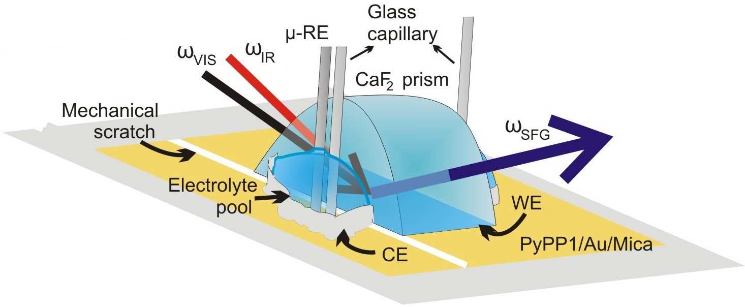
In order to perform SFG measurements under E–control in electrochem- ical media, a thin–layer analysis cell [55] was modified (Fig. 1) by building electrolyte (0.1 M NaOH) reservoirs at the sides of the CaF2 prism using a chemically resistive two-component adhesive (X60, HBM Inc., USA). Two


Figure 1: Sketch of the beam path and the arrangement of the electrodes in the modified thin–layer analysis cell for SFG measurements. The reflected VIS and IR beams are not glass capillaries containing a part of the electrolyte solution were dipped into each of the electrolyte pools and slowly released electrolyte into the reser- voir during the measurements in order to compensate evaporation in dry air conditions. PyPPx /Au/Mica substrates underlying the prism were extended over the larger side of the prism into the reservoir. Au films on the substrates were separated into two parts at the boundary between the prism and reser- voir by a mechanical scratch so that the part underneath the prism served as working electrode (WE) and the other part within the reservoir as counter electrode (CE). An Ag/AgCl (3 M KCl) microreference electrode (RE) was placed next to the prism in order to minimize the potential drops. In this configuration, the area exposed to the incident beams was approximately 0.5 cm away from the reference and counter electrodes. The thickness of the electrolyte layer underneath the CaF2 was estimated to be <1 µm, which enabled homogenous potential control over the entire sample surface. Right after the assembly of the electrochemical SFG cell, a series of spectra with an exposure time of 0.4 s in the background-suppressed mode was started. Af-


j / m
E vs. (Ag/AgCl) / V -1.8 -1.6 -1.4 -1.2 -1.0 -0.8 -1.8 -1.6 -1.4 -1.2 -1.0 -0.8 E vs. (Ag/AgCl) / V
E vs. (Ag/AgCl) / V
E vs. (Ag/AgCl) / V
Figure 2: First and second CV scan cycles obtained from (a) PyPP1-modified Au(111) and (b) PyPP2-modified Au(111). In (a) a voltammogram of bare Au(111) is also given (dashed line). (a◦) and (b◦) show an enlarged view around the cathodic and anodic peaks of (a) and (b), respectively. (c) PyPP1-modified poly-Au in 0.1 M NaOH. The inset shows the zoom of the low-current region of the first cycle. Subsequent scans yielded similar peaks but with smaller intensities as a result of partial readsorption of thiolates.
ter 10 recorded spectra at the open circuit potential (OCP), the potentiostat was switched on performing a CV starting from the first vertex at 0 V to the second vertex at -1.6 V with a scan rate of 50 mV s−1. The SFG signal was then continuously recorded for 10 CV cycles. For obtaining a quantitative measure of the SFG signal, the recorded background-suppressed spectra were integrated without any further data treatment.
3. Results and Discussion 3.1. Cyclic Voltammetry (CV) Fig. 2 presents the CVs obtained for the SAM–modified Au electrodes in 0.1 M NaOH and compares them to the curve for pure Au(111). Adsorption sites on an Au(111) surface differ for PyPP1 and PyPP2 because of differ- ent molecular tilt angles arising from the "odd-even" effect involving the methylene spacers [57]. PyPP1 adsorbs on Au(111) with a (2 3 × 3)R30◦ overlayer structure, whereas PyPP2 yields a (5 3 × 3)rect structure on the same substrate [57]. The 25% lower surface coverage of PyPP2 on the surface results in weaker intermolecular interactions compared to PyPP1 [46, 57].
Hence, desorption potentials (C1 peaks in the CVs) of the dilute PyPP2 SAM and the compact PyPP1 SAM differ accordingly. Although C1 peak potentials vary between PyPP1– and PyPP2–modified Au(111) electrodes, both systems yield double peaks within the electroreductive desorption re- gions, as shown in Fig. 2a and b, respectively. For the PyPP1/Au(111) electrode, the C1 peak at -1.30 V is followed by a much larger second peak C2 at -1.47 V. By integration of these peaks, Q ∼-0.06 mC cm-2 for C1 and -1.32 mC cm-2 for C2. For desorption of a PyPP1 SAM with the given overlayer structure on Au(111), a total Faradaic charge of ∼-0.06 mC cm-2 is expected according to Faraday's Law for a single electron transfer process, Γ = Q/F , where Γ is the surface coverage, and F is the Faraday constant.
The experimental results show the major portion of the theoretically esti- mated charge for desorption of a complete monolayer to be reached during the C1 peak. Remarkably, the integrated current of the C2 peak corresponds to a 22–times larger reductive charge, which results obviously from a Faradaic process other than thiol desorption. The peak current, hence also the reac- tion rate, in this second cathodic peak is ∼10 times higher than the current at the same potential on bare Au(111) during the first cycle, and is still ∼3 times as high as bare Au(111) during the second cycle. In the voltammogram of the PyPP2/Au(111) electrode, the C1 peak at -1.11 V yields Q ∼-0.06 mC cm-2, similar to PyPP1/Au(111). Subsequently, a much less pronounced C2 peak appears at -1.42 V with Q ∼-0.01 mC cm-2. A direct relationship be- tween monolayer structure and the rate of the concomitant Faradaic reaction is reflected in the CVs of compact PyPP1 and non–compact PyPP2 SAMs on Au(111). According to a model, compact monolayers such as PyPP1 desorb via a homogeneous reduction process all over the electrode surface, whereas etching centers are created in more permeable monolayers and desorption propagates successively at the edges of these etching centers [58, 59]. The lower ionic permeability expected for PyPP1 is supposed to cause slower dif- fusion of counter ions (here Na+) from the electrolyte to the sulfur heads through the thiols, consequently shifting the desorption potential to more negative values [46].
The observed extraordinary voltammetric response upon the electrore- ductive desorption of PyPP1 SAMs becomes even more striking when the monolayer is adsorbed on a poly-Au surface instead of Au(111). For the PyPP1/poly-Au electrode, again a double peak is observed in the voltam- mogram (Fig. 2c). However, the C'1 peak is barely visible next to the massive C'2 peak. (Here, the peaks are designated as C'1 and C'2 to stress the slight differences in origin of the peaks.) A Q ∼-0.01 mC cm-2 for the first peak at -1.15 V suggests that in this peak, only a small portion of the monolayer desorbs, which most likely consists of weakly bound thiols, e.g. at domain boundaries. The residual major portion of the monolayer desorbs at more negative potentials in the dominant second peak at -1.61 V. Integration yields Q ∼-2.30 mC cm-2 for C'2. Obviously, on a poly-Au substrate, the PyPP1 SAM desorbs at more cathodic potentials compared to an Au(111) substrate.
At the same time, larger reductive currents are observed. The negative po- tential shift for desorption of the monolayer on a poly-Au substrate compared to Au(111) can be explained by the increased electrochemical stability of the monolayer on the polycrystalline surface. It is well-known that the energy required to desorb SAMs from a gold surface is minimum for Au(111) [60– 63]. Assuming that the poly-Au substrate has a considerable proportion of low index surfaces other than (111), desorption at more negative potentials is quite reasonable. However, it is astonishing that by using a poly-Au sub- strate, the additional Faradic reaction overlaps with the desorption reaction, yielding a 75% larger Q compared to the PyPP1/Au(111) electrode.
Further CV measurements at different scan rates (not shown, see also Section 3.3) indicate that the C2/C'2 peak is related to a diffusion–controlled reaction at the corresponding peak potential. On the other hand, the area under the C1/C'1 peak (i.e. the charges) is almost independent of the scan rate, as expected for a peak purely related to desorption.
The CV results show that the main body of the monolayer desorbs from a poly-Au substrate within the range of the C'2 peak. However, for the PyPP1/Au(111) system, both peaks are large enough to contain desorption currents of a monolayer so that the origins of the corresponding peak cur- rents cannot be distinguished. For determining the beginning and the end of the monolayer desorption process on this system, changes at the elec- trolyte/PyPP1/Au interface during a CV scan were tracked using ellipsom- (b) −1.5
E / V (Ag AgCl) 0 −1.5 −1 −0.5 0 E vs. (Ag/AgCl) / V Figure 3: Real part of J1 averaged from 340-360 nm (◦, scale on the left, see text forrationale of wavelength range) during (a) the first and (b) the second CV scan (—, scale on the right) of PyPP1/Au(111) in 0.1 M NaOH. (a) includes Re(J1) (--) on Au(111) without SAM. Arrows indicate the respective potential scan direction. Scan rate: 5 mV 3.2. Ellipsometry Fig. 3a shows the real part of J1 as function of E during the first CV scan of a freshly prepared PyPP1/Au(111) sample. Different from the previously presented CV measurement (Fig. 2a), in this experiment the scan rate was set to 5 mV s−1 for achieving a good synchrony between the applied potentials and ellipsometric data acquisition. A significant decrease is observed in the current of the second peak compared to the preceding first peak at this low Taking a look at the corresponding ellipsometry data, a stable and con- stant Re(J1) is observed until the onset of the C1 peak. The magnitude observed of Re(J1) ∼ −1 nm in the given wavelength range is expected for an organic layer of a thickness of ∼1.5 nm, consistent with an intact SAM.
The wavelength–dependence of the data is mainly given by the wavelength– dependence of ǫ2, which means that the curves appear similar in shape but different in magnitude at all wavelengths. The wavelength range displayed here was chosen as it is the region where ǫ2 is closest to 0, which simplifies the analysis according to Eq. 1. At the onset of the C1 peak in the CV, Re(J1) increases and reaches zero approximately in the middle of the desorption peak. Re(J1) = 0 corresponds to a complete absence of a layer, or the can- cellation in Eq. 1 of the effect of regions with positive or negative dielectric constant contrast. Re(J1) continues to rise above zero until the onset of the C2 peak, and remains constant with further increasing cathodic potentials until the potential vertex at -1.6 V. The positive value of Re(J1) implies that the dominating layer in the interfacial refractive index profile now has a real part of the dielectric constant at the respective frequency between the value of the electrolyte (∼1.8) and Au (∼-1.1), which is untypical for organic mate- rials. During the reverse scan, re-adsorption is observed as a slight decrease in Re(J1), which remains at values >0. Readsorption is barely visible in the CV current, because the scan rate is not high enough to display respective charges. The results obtained during the subsequent second scan are shown in Fig. 3b. In the direction of increasing cathodic potential, Re(J1) resembles closely the backward scan of Fig. 3a. Desorption is barely visible in Re(J1), but it is in the CV. In the backward scan, values of Re(J1) approach more and more the value of 0. The increased fluctuations in Re(J1) in the later stages of the experiment are attributed to the presence of H2 bubbles, which remain on the surface after E is entering the regime of HER for the first time, and the consequent increase in scattered light intensity on the expense of the detected reflected intensity. It must be pointed out that the changes in the curves between the different scans are not due to drift of the instrument, but are caused by genuine changes in the interfacial structure. Corresponding experiments with bare Au show highly repeatable scans.
The presented ellipsometry results reveal information about the state of the PyPP1/Au interface during electrochemical polarization. The main change in Re(J1) is observed during the first forward CV scan between the C1 and C2 peaks. In this potential regime, desorption of the SAM occurs, however, its constituents remain present near the interface. During subse- quent readsorption, Re(J1) is still far away from its initial value and even shows opposite sign to the initial value. One might expect that the SAM loses all order during the desorption process, but SFG measurements, which will be discussed later, show that order is maintained in the course of des- orption, and is also maintained over at least 10 CV cycles. The most likely explanation for the large effect in the first scan compared to all other is that desorption leads to the presence of a layer or patches of low refractive index between SAM and Au surface or between SAM and electrolyte. The value of Re(J1) ∼ 2 nm after the desorption can be explained by the presence of an effectively ∼2.6 nm thick layer of a material with ǫs = 1, if a total loss of the SAM is assumed. As the SAM is still present, the effective layer thickness must be even higher. The presence of macroscopic H2 bubbles, which are visible below -1.4 V, cannot account for the observed effect. Macroscopic bubbles barely affect Re(J1), as has been confirmed in control experiments in the absence of a SAM. Results from one control experiment are shown in Fig. 3a. The aforementioned layer of low refractive index is likely in part to be consisting of adsorbed H2, which starts to form below the desorption potential. As not all gas is removed from the system when scanning in an- odic direction, it may remain adsorbed, explaining the large and irreversible shift to positive values of Re(J1). Further, desorption may also lead to sub- stantial changes in the electronic structure of the Au surface, resulting in respective irreversible changes of the dielectric function of Au near the inter- face. A third possibility is a substantial change in solvent structure around the desorbed SAM. This last explanation is, however, unlikely, because even relatively large changes result only in rather weak effects on the dielectric constant at optical frequencies.
It is also worth to underline an important result from the comparison of the ellipsometric and CV results. The intensities of the two voltammetric peaks and the degree of shift in Re(J1) do not match. This observation indicates different mechanisms as the sources of the two subsequent cathodic peaks on the voltammograms of PyPP1/Au(111) samples. Consequently, the first reductive peak can be assigned mainly to the desorption of the SAM.
In order to elucidate the origin of the large excess currents appearing as the second peak on PyPP1/Au(111) and overlap with the desorption currents inside the same peak on PyPP1/poly-Au systems, further investigations were done by hydrodynamic voltammetric measurements.
3.3. Hydrodynamic voltammetry So far, the observed excess cathodic charges were postulated to result mainly from a parallel Faradaic reaction concomitant to desorption of a PyPP1 monolayer. HER is a likely candidate as the possible source of the generated currents, because these excess currents are observed at potentials where HER is thermodynamically possible [46]. In order to confirm the role of H2, RRDE measurements were performed using a PyPP1/poly-Au disk electrode surrounded by a Pt ring, which was also modified with PyPP1 monolayer without extermination of the H2 sensitivity. Fig. 4 shows the voltammograms for the ring and disk electrodes at 900 RPM angular rotation speed in 0.1 M NaOH. Both the ring and the disk voltammograms look quite symmetrical. Similar to the CV shown in Fig. 2c, the PyPP1/poly-Au disk electrode shows a desorption-related large cathodic peak covering a potential range between -1.4 V and -1.7 V. On the ring electrode, a corresponding oxidative peak is observed. After correction of the ring voltammogram re- garding its collection efficiency, the absolute value of the charge underneath the anodic peak on the ring corresponds to ∼90% of the of the cathodic peak charge on the disk voltammogram. The relation between the ring and / m
j
R
/ m
j
D
E vs. (Ag/AgCl) / V
E vs. (Ag/AgCl) / V
Figure 4: (a) RRDE data. Voltammograms obtained from PyPP1/poly-Au disk (jD) and PyPP1/Pt ring (jR) during the first scan cycle in 0.1 M NaOH with 900 RPM angular rotation speed and 50 mV s−1 scan rate. Ring potential was fixed at -0.5 V. (b) RDE data. Voltammograms of PyPP1/poly-Au electrode in 0.1 M NaOH at various angular rotation speeds ω. The inset shows the reductive charge density vs.
disk currents is only approximate, because the determination of the collec- tion efficiency of a thiol modified ring is prone to errors. Nonetheless, since readsorption of released thiolates on the thiol modified ring can be ruled out, this anodic peak can be assigned mainly to oxidation of H2 that is formed on the disk electrode concomitant to desorption of the monolayer. The observed C2 and C'2 peaks in the CVs can therefore be related to the evolution of H2.
Because in this peak, the HER is significantly faster than on bare Au, the term "rapid HER" will be used here to described this special kind of HER.
In order to investigate the relationship between HER kinetics and SAM desorption, further hydrodynamic voltammetry experiments were carried out using identical PyPP1/poly-Au electrodes at varying electrode angu- lar rotation speeds. A series of the hydrodynamic voltammograms for the PyPP1/poly-Au electrodes is presented in Fig. 4b. At each rotation speed the cathodic peak corresponding to C'2 is visible. However, the peak potential of the large peak gradually shifts to more anodic potentials with increas- ing rotation rates. Under hydrodynamic conditions, after cleavage of the S-Au bonds, thiolates are expected to diffuse faster away from the double layer region at high rotation speeds, as shown in previous experiments [64].
The transport of H2 away from the electrode is also likely to contribute to transport of thiolates away from the electrode surface. At slower rotation, thiolates suspended in the double layer should slow down desorption of the remaining thiols [64]. Therefore, a SAM desorbs at slightly more anodic po- tentials when the electrode rotation speed is increased. For the investigated PyPP1/poly-Au electrodes, the total potential shift amounts to 60 mV (from -1.61 V to -1.55 V) between 0 and 4000 RPM. Due to the association between SAM desorption and rapid HER, the reductive peaks shift without chang- ing their shape. Interestingly, peak charges decrease with increasing angular rotation speed (inset in Fig. 4b). These results indicate that retention time of the desorbed PyPP1 molecules has an influence on the HER kinetics. At this point, it becomes critical to know in what structural state the thiolates reside above the Au surface after desorption. The following experiment using vibrational SFG spectroscopy addresses this question.
3.4. SFG vibrational spectroscopy For monitoring order of thiol/thiolate molecules during voltammetric scans, SFG spectroscopy was applied both in situ and in real time. Measure- ments were performed using Au(111) substrates, because flat surfaces are re- quired to obtain adequate spectroscopic data. In addition to PyPP1/Au(111), a PyPP2/Au(111) sample was investigated for comparison, which has a dif- ferent structural quality and voltammetric response with less pronounced additional Faradaic contributions, as shown in Fig. 2.
Fig. 5a shows the first one and a half voltammetric cycles of a typical SFG experiment. The spectrum shows an SFG band attributed to the ring vibration of the pyridine moiety of PyPP1, centered around 1600 cm−1 [57].
This mode was chosen because a measurement of the full SFG spectrum has shown this band to be extremely intense. This extremely high intensity is required for real-time measurements during the CVs. The evolution of the signal intensity over time is alternating presumably due to nonlinear χ(3) effects related to the coupling of visible, IR and static electric field at the interface, which is discussed in detail elsewhere [65]. No further significant change is observed in the intensity curve during the voltammetric scan, not even in the peak potential regions below -1.25 V. This stable alternating sig- nal indicates that the two–dimensional crystalline order of the monolayer is persevered at all applied potentials. The SFG signal obtained from ordered PyPP1 structures is not necessarily acquired only from the thiols directly present on the Au(111) surface but also from the surface plane of the electri- cal double layer. The first two CV scans recorded in parallel of SFG spectral aquisition are shown in 5 b. The curves are slightly different compared to those in Fig. 2, because of the different cell geometry. Especially the read- sorption peak is more pronounced. Overall, CV data shows that after each cycle, the amount of the readsorbed molecules becomes smaller. Hence the observed stable SFG signals comprise contributions of both adsorbed and suspended molecules as long as they remain ordered. In Fig. 5c the nor- malized integrated SFG signals are plotted as function of the number of CV cycles the electrode was subjected to. Because the intensity of the signal is related to the order, number density, and orientation of molecules, a decrease in the maximum intensity value indicates loss in the structural molecular ar- rangement within the surface plane. Astonishingly, the signal obtained from PyPP1 does not show significant variations after 10 voltammetric scan cy- cles between 0 V and -1.6 V. On the other hand, the intensity for PyPP2 decreases continuously after each cycle. After 10 cycles, the PyPP2 signal has almost vanished completely due to loss of order and/or decreased num- ber density within the SAM. After leaving the PyPP1 monolayer at open circuit for ∼30 min after desorption experiments, the signal of PyPP1 has also completely disappeared, indicating a diffusion of the molecules from the surface into the bulk.
It is worth noting that readsorption peaks in the CVs of Section 3.1, as well as those measured in the CVs during SFG experiments, are small, considerably smaller than the desorption peaks. In a previous work, read- sorption was quantified of PyPP1 and PyPP2 between -0.2 and -1.8 V [46]: 25 % of PyPP1 and ∼50 % of PyPP2 readsorb after each cycle. However, the molecules remain physisorbed to the electrode surface, even though the Au-S bond is broken. SFG vibrational spectra do not distinguish between ordered layers covalently bound to Au and ordered layers physisorbed to Au.
Therefore, the presence in the SFG spectra of the characteristic vibrational mode from the molecules shows layer order, and hence also PyPPx presence, in the interfacial region.


I / m -0.2
E vs. (Ag/AgCl) / V
er / c 1400
Figure 5: (a) Evolution of a pyridine ring vibration of PyPP1 on Au(111) during potential sweeps from 0 V to -1.6 V, back to 0 V, to finally -1.6 V, corresponding to one and a half CV cycles, as measured with SFG vibrational spectroscopy. (b) First two CV scans recorded in the SFG cell during aquisition of spectra shown in (a). (c) Integrated SFG intensity of the observed band from PyPP1/Au(111) and PyPP2/Au(111) during ten CV cycles. The integrated SFG signals are normalized to the maximum signal obtained from an ordered SAM for each thiol.
3.5. Discussion of rapid HER origin The combination of the voltammetric and spectroscopic results obtained from PyPP1 and PyPP2 modified Au samples reveals two important features that make the desorption process especially of PyPP1 extraordinary com- pared to the desorption of any aliphatic or short araliphatic thiol reported to the author's knowledge. The first extraordinary feature is the preserva- tion of two–dimensional order of the reductively desorbed thiolates within the double layer region, that exists over a long period of time and a large potantial range after desorption. The second feature is the association of rapid HER with the desorption of the SAMs. These two features are closely related, considering the observed differences in desorption between PyPP1 and PyPP2 SAMs. The correlation between these features helps to interpret the complicated voltammetric desorption behavior on a solid ground.
Previous studies with aliphatic thiols showed that the structure of the desorbed thiols undergoes a transition from upright molecular oriented films to aggregates [26, 27, 29, 30, 66], or a striped phase with flat lying dithiol molecules [67], in the electrochemical double layer region. Based on subtrac- tively normalized interfacial infrared spectra [27, 66], and in situ scanning tunneling microscopy studies [26], aggregates of long n-alkanethiolates have been proposed to be in form of micelles. The micelle formation process involves a competition between repulsive forces among negatively charged sulfur head groups, attractive van der Waals forces among the chain units, and hydrophobic forces. Hydrophobic termination groups accelerate micelle formation. Taking all attractive and repulsive contributions into account, the shape of the aggregates can be estimated from the semiempirical "packing parameter" v/(a0lc) involving the optimal surface area a0 of the molecu- lar head group, chain length lc, and chain volume v [68]. For hydrocar- bon amphiphiles, micelle formation becomes favorable if v/(a0lc) < 1/3 [68].
Due to the small v/(a0lc) of the long aliphatic thiols with conformational disorder in the desorbed state, micelle formation is conceivable for the n- alkanethiolates. On the other hand, as the araliphatic chain is rather rigid, araliphatic molecules exhibit a shape close to a cylinder, where v/(a0lc) ∼ 1.
This value of v/(a0lc) implies favorable formation of planar aggregate struc- tures. Consequently, loss of crystalline order after reduction is expected to occur slower for long araliphatic thiols. According to the SFG spectroscopy measurements, for the thiolates of PyPP1 the crystalline structures inherited from the chemisorbed monolayer are preserved in both voltammetric peak re- gions (Fig. 5). According to the structural differences between PyPP1 and PyPP2 monolayers, an even more stable ordered thiolate structure is ex- pected for the compact PyPP1 SAM, which is confirmed by the presented SFG results. These results are clear indication of the astonishingly long life- time of the ordered thiolate structures for the investigated SAMs, especially Apart from the stable structural order of the desorbed thiolates, a sec- ond striking result is the detection of HER concomitantly to desorption of the PyPP1 monolayer. On poly-Au, a rapid HER was found to occur si- multaneously with the desorption of the main fraction of the SAM. On the other hand, based on the ellipsometry results, these two reactions are not simultaneous on Au(111) surfaces, were HER is found to occur only after desorption of the SAM. Both processes and are observed as separate peaks in voltammograms (Fig. 3). The first reductive peak originates mainly from SAM desorption, as confirmed by shift in Re(J1) at the corresponding po- tentials. Because no pronounced shift in Re(J1) is detected in the potential region of the subsequent large peak, it can be deduced that this peak consists mainly of HER currents. When the rapid HER starts, the surface is already saturated with H2, so the main fraction of the additionally produced H2 is leaving the system as gas, therefore it is not present in the interfacial region.
This finding can be generalized for the other members of the araliphatic thiol series, including PyPP2, which also yields excess cathodic currents in parallel to the thiol reduction process as observed on Au(111) surfaces.
Considering the results of the RDE measurements, a relationship between the rate of the HER (hence, catalytic activity of a surface towards HER) and the thiolate's lifetime in the surface plane of the electrode is observed. The presented voltammograms obtained from PyPP1/poly-Au electrodes (Fig.
4b) show that peak currents become smaller at faster electrolyte convection rates. Smaller peak currents in case of shorter lifetime of thiolates in the double layer region indicate a catalytic activity on the Au electrode through the presence of desorbed thiolates. A similar behavior was observed with PyPP1/Au(111) electrodes; the second H2-related peak became smaller com- pared to the first desorption-related peak when the CVs were recorded with a lower scan rate (comparing Fig. 2a and Fig. 3a). Altogether these observa- tions indicate a diffusion–related phenomenon. The catalytic effect observed for HER requires the presence PyPP1 monolayers on the electrode surface without covalent bond to the electrode.
The above–stated arguments lead to models for the overall desorption mechanism of the investigated thiols. First, consider the desorption of PyPP1.
As shown in Reaction 1, thiol desorption requires exchange of electrons be- tween Au substrate and thiols. This reaction, however, involves also the substitution of thiol molecules with water on the Au surface [35], (ads) + ne– + xH2O −→ nRS(aq) + (x−y)H2O(ads).
Since Reaction 2 (where y stands for the number of water molecules required for the solvation of the thiolate) occurs at sufficiently negative potentials for HER, the adsorbed water layer is immediately consumed for formation of 2O(ads) + e– −→ Reactions 2 and 3 are reactions that occur for any type of thiol on an Au surface. It must be pointed out that the participation of HER in the desorp- tion process leads to an current contribution also, which may account for the fact that the integrated desorption currents are slightly higher than required for monolayer desorption. In this specific case, especially for desorption of PyPP1, the question arises: What is the reason of the temporary acceleration of Reaction 3? In the following, several possible models will be discussed.
The overall model is schematically summarized in Fig. 6.
One possible reason for high HER rates associated with desorption is the retarded surface reconstruction of the Au substrate. It is currently widely accepted that thiolate bonding on Au results in a lower density of Au surface atoms compared to the SAM–free surface. SAM formation involves displace- ment of Au atoms on the surface; lifting the Herringbone reconstruction and formation of vacancy islands (etch pits). Recent studies demonstrated that Figure 6: Schematic view of the proposed model for the rapid HER. (a) shows the intact SAM, which is reductively desorbed (b). Subsequent transport of water into the region between desorbed monolayer and Au leads to H2 evolution (c).
together with vacancy islands, additional Au adatoms are formed, which serve as energetically favoured bonding sites for thiolates [69–71]. Compared to a reconstructed surface, such a modified Au surface underneath the SAM may offer more catalytically active sites for reactions such as HER, if it becomes accessible to the electrolyte. However, it has been reported for alkyl-thiols that desorption of the SAM immediately initiates surface reconstruction, in- cluding formation of the herringbone structure on Au(111), roughening of step edges, formation of gold islands and disappearance of vacancy islands [30, 72–74]. However, because the adsorption of the aliphatic and araliphatic thiols result in the same changes on an Au surface [43, 57], a similar recon- struction mechanism is expected for both thiol types after reductive desorp- tion. For aliphatic thiols, no increase in the HER rate is, however, observed.
As a result, a substantial difference on the Au surface after reductive desorp- tion of aliphatic and araliphatic SAMs is unlikely but cannot be completely ruled out here.
Catalysis of HER through physical interactions between the Au surface and any units of the desorbed thiolates, e.g., the pyridine moiety, can be safely ruled out as a possible explanation, due to the orientation of thiolates in the related potential region. In this orientation, only the sulfur heads are facing to the Au surface, separated from the Au surface by an electrolyte gap of ∼1 nm [75, 76]. Assuming a similar separation distance for PyPP1 thio- lates, a strong influence of the ordered, suspended thiolates on the structure of the electrolyte between Au and desorbed SAM is expected. In any assem- bly form, the suspended negatively charged thiolates are prone to interactions with counter ions in the solution. Protonation of electroreductively desorbed n-alkanethiolates has been suggested despite the high solution pH [77, 78].
However, at pH 13, protonation of the full monolayer is not expected, as the pKa values for HS-R units are usually lower,[78] e.g. for C6H5-CH2-SH, The most likely mechanism for the observed acceleration of the HER after reductive desorption of the thiol SAM involves orientation of water molecules in the gap between Au and suspended monolayer. Diffusion of positively charged counter ions, in this case Na+ , from the electrolyte is essential for desorption of SAMs [77]. If the desorbed thiolates form aggregates, a homogenous charge distribution on the Au surface is quickly established.
On the other hand, if the organic layer does not lose its two-dimensional order after desorption, as observed here, Na+ will be present in a hydrated form between the negatively charged thiolate and the negatively polarized Au surface (Fig. 6b). This additional layer of hydrated positive ions in the gap between the organic layer and the Au surface is suggested here to lead to an optimum pre-orientation of water for a participation in the HER, and consequently higher HER rates (Fig. 6c). The ideal orientation of water needed for participation in the HER is not known. Two possible candidates are marked in Fig. 6c, though to achieve direct experimental evidence is The suggested model for the catalysis of HER — though speculative at this point — can be employed to explain the double peaks observed on the voltammograms upon desorption of the SAMs. For the catalytic activity through water reorientation, transport of Na+ from bulk solution into the gap between the thiolate monolayer and the Au surface is required. PyPP1 thiolates with orientation as observed are not prone to electrolyte penetra- tion through the suspended film. Water and ion transport from the bulk electrolyte into the volume between Au and suspended monolayer occurs through inherent structural defects in the organic monolayer, such as do- main boundaries. On an Au(111) surface, after consumption of the initially adsorbed water layer, further water transport into the inner plane requires additional time due to the existence of large electrolyte–blocking SAM do- mains and a low amount of defects in the thiolate layer. Therefore, currents from the catalyzed HER are seen in a peak that is separated from the thiol reduction peak (Fig. 2a), and in general currents show a diffusion–related behavior in the electrochemical experiments. On poly-Au, due to the higher amount of structural defects in the SAM, electrochemical desorption and subsequent transport of electrolyte into the gap occur much faster, so that currents from both Faradaic reactions overlap (Fig. 2c). With increasing amount of water molecules in the gap between the suspended thiolate layer and the Au surface, contribution of HER to the peak currents increases. In the proposed mechanism, depletion of thiolate molecules causes loss of the observed catalytic activity, because the optimum distribution of Na+ pends on the existence of the oriented thiolates in the double layer. Because the suspended thiolate layer also hinders the transport of the produced H2 gas from the Au surface, the observed rate increase does not last long. In addition to formation of macroscopic bubbles, which are observed at strongly cathodic potentials only, the formed H2 can be adsorbed either between Au and suspended SAM, or at the SAM/electrolyte interface.
An accelerated ("rapid") HER has been detected concurrent to desorp- tion of structurally stable PyPP1 SAMs. The rate of the HER is strongly influenced by the structure of desorbed thiolates residing near the electrode surface after desorption. In situ ellipsometry results show a decrease of the interfacial refractive index upon SAM desorption. Combined electrochemical and SFG spectroscopy investigations show that after electroreductive desorp- tion, the structural order of the araliphatic thiol films is inherited from the chemisorbed state. For the compact PyPP1-SAM the two-dimensional or- der is astonishingly stable. Comparison with the less compact PyPP2-SAM, where two–dimensional order is not persevered upon reductive desorption, as well as with literature data on aliphatic SAMs, shows that the structural sta- bility of the desorbed SAM is a prerequisite for the occurrence of the increase in HER rate.
The results imply that the presence of a highly ordered adsorbed layer of non–redox active species can increase, rather than decrease, the rate of an interfacial electron transfer reaction, in this case of the HER, here likely due to the ordering effect of the organic monolayer on the solvent and reagent wa- ter. The ordering effect occurs via the transient species of thiolates residing in the double layer region immediately after cleavage of the Au-S bond. The stability of the SAM after desorption is crucial for the observed effect. The exact nature of the interfacial water requires detailed investigations from a combination of vibrational spectroscopies and molecular simulations.
M.I.M. thanks the IMPRS SurMat for a scholarship. A. Terfort gener- ously provided the substances for this study. M. Stratmann is acknowledged for his continuous support. C.B. and P.K. acknowledge support from the Helmholtz Program BioInterfaces and P.K. from NIH Grant EB-002027 to the National ESCA and Surface Analysis Center for Biomedical Problems.
Y. C. thanks for support from the European Union and the state of North Rhine-Westphalia in the frame of the HighTech.NRW program.
[1] S. B. Sachs, S. P. Dudek, R. P. Hsung, L. R. Sita, J. F. Smalley, M. D.
Newton, S. W. Feldberg, C. E. D. Chidsey, Rates of interfacial electron transfer through π-conjugated spacers, J. Am. Chem. Soc. 119 (1997) [2] D. M. Adams, L. Brus, C. E. D. Chidsey, S. Creager, C. Creutz, C. R.
Kagan, P. V. Kamat, M. Lieberman, S. Lindsay, R. A. Marcus, R. M.
Metzger, M. E. Michel-Beyerle, J. R. Miller, M. D. Newton, D. R. Roli- son, O. Sankey, K. S. Schanze, J. Yardley, X. Zhu, Charge transfer on the nanoscale: current status, J. Phys. Chem. B 107 (2003) 6668.
[3] N. K. Chaki, K. Vijayamohanan, Self-assembled monolayers as a tunable platform for biosensor applications, Biosens. Bioelectron. 17 (2002) 1.
[4] J. Gooding, F. Mearns, W. Yang, J. Liu, Self-assembled monolayers into the 21st century: Recent advances and applications, Electroanalysis 15 [5] M. Frasconi, F. Mazzei, T. Ferri, Protein immobilization at goldthiol surfaces and potential for biosensing, Anal. Bioanal. Chem. 398 (2010) [6] T. Baunach, V. Ivanova, D. Kolb, H.-G. Boyen, P. Ziemann, M. B¨ P. Oelhafen, A new approach to the electrochemical metallization of organic monolayers: Palladium deposition onto a 4,4-dithiodipyridine self-assembled monolayer, Adv. Mater. 16 (2004) 2024.
[7] C. Silien, D. Lahaye, M. Caffio, R. Schaub, N. R. Champness, M. Buck, Electrodeposition of palladium onto a pyridine-terminated self-assembled monolayer, Langmuir 27 (2011) 2567.
[8] M. I. Muglali, J. Liu, A. Bashir, D. Borissov, M. Xu, Y. Wang, C. Woll, M. Rohwerder, On the complexation kinetics for metallization of or- ganic layers: palladium onto a pyridine-terminated araliphatic thiol film, Phys. Chem. Chem. Phys. 14 (2012) 4703.
[9] M. Rohwerder, M. Stratmann, Surface modification by ordered mono- layers: New ways of protecting materials against corrosion, MRS Bull.
24 (1999) 43.
[10] J. Mathiyarasu, S. Pathak, V. Yegnaraman, Review on corrosion pre- vention of copper using ultrathin organic monolayers, Corros. Rev. 24 [11] F. Caprioli, F. Decker, A. G. Marrani, M. Beccari, V. D. Castro, Copper protection by self-assembled monolayers of aromatic thiols in alkaline solutions, Phys. Chem. Chem. Phys. 12 (2010) 9230.
[12] M. I. Muglali, A. Bashir, M. Rohwerder, A study on oxygen reduc- tion inhibition at pyridine-terminated self assembled monolayer modified Au(111) electrodes, Phys. Status Solidi A 207 (2010) 793.
[13] A. Nowicka, U. Hasse, G. Sievers, M. Donten, Z. Stojek, S. Fletcher, F. Scholz, Selective knockout of gold active sites, Angew. Chem., Int.
Ed. 49 (2010) 3006.
[14] T. Uchida, H. Mogami, A. Yamakata, Y. Sasaki, M. Osawa, Hydro- gen evolution reaction catalyzed by proton-coupled redox cycle of 4,4- bipyridine monolayer adsorbed on silver electrodes, J. Am. Chem. Soc.
130 (2008) 10862.
[15] R. Alkire, D. Kolb, J. Lipkowski, P. Ross, Chemically Modified Elec- trodes, Wiley-VCH, Weinheim, 2009.
[16] M. Rohwerder, K. de Weldige, M. Stratmann, Potential dependence of the kinetics of thiol self-organization on Au(111), J. Solid State Elec- trochem. 2 (1998) 88.
[17] F. Ma, R. B. Lennox, Potential-assisted deposition of alkanethiols on Au: Controlled preparation of single- and mixed-component SAMs, Lang- muir 16 (2000) 6188.
[18] M. J. Esplandi´ u, H. Hagenstr¨om, D. M. Kolb, Functionalized self- assembled alkanethiol monolayers on Au(111) electrodes: 1. Surface structure and electrochemistry, Langmuir 17 (2001) 828.
[19] N. Darwish, P. K. Eggers, S. Ciampi, Y. Zhang, Y. Tong, S. Ye, M. N.
Paddon-Row, J. J. Gooding, Reversible potential-induced structural changes of alkanethiol monolayers on gold surfaces, Electrochem. Com- mun. 13 (2011) 387.
[20] J. Zhang, A. C. Welinder, Q. Chi, J. Ulstrup, Electrochemically con- trolled self-assembled monolayers characterized with molecular and sub- molecular resolution, Phys. Chem. Chem. Phys. 13 (2011) 5526.
[21] W. Wang, S. Zhang, P. Chinwangso, R. C. Advincula, T. R. Lee, Electric potential stability and ionic permeability of sams on gold derived from bidentate and tridentate chelating alkanethiols, J. Phys. Chem. C 113 (2009) 3717.
[22] C. A. Widrig, C. Chung, M. D. Porter, The electrochemical desorption of n-alkanethiol monolayers from polycrystalline Au and Ag electrodes, J. Electroanal. Chem. Interfacial Electrochem. 310 (1991) 335.
[23] T. W. Schneider, D. A. Buttry, Electrochemical quartz crystal microbal- ance studies of adsorption and desorption of self-assembled monolayers of alkyl thiols on gold, J. Am. Chem. Soc. 115 (1993) 12391.
[24] P. Krysinski, R. V. Chamberlain, M. Majda, Partial electron transfer in octadecanethiol binding to gold, Langmuir 10 (1994) 4286.
[25] D.-F. Yang, C. P. Wilde, M. Morin, Electrochemical desorption and adsorption of nonyl mercaptan at gold single crystal electrode surfaces, Langmuir 12 (1996) 6570.
[26] D. Hobara, K. Miyake, S.-I. Imabayashi, K. Niki, T. Kakiuchi, In- situ scanning tunneling microscopy imaging of the reductive desorption process of alkanethiols on Au(111), Langmuir 14 (1998) 3590.
[27] M. Byloos, H. Al-Maznai, M. Morin, Formation of a self-assembled monolayer via the electrospreading of physisorbed micelles of thiolates, J. Phys. Chem. B 103 (1999) 6554.
[28] A. Bad´ıa, Asymptotic theory for the inverse problem in magnetic force microscopy of superconductors, Phys. Rev. B 60 (1999) 10436.
[29] S.-S. Wong, M. D. Porter, Origin of the multiple voltammetric des- orption waves of long-chain alkanethiolate monolayers chemisorbed on annealed gold electrodes, J. Electroanal. Chem. 485 (2000) 135.
[30] H. Wano, K. Uosaki, In situ, real-time monitoring of the reductive des- orption process of self-assembled monolayers of hexanethiol on Au(111) surfaces in acidic and alkaline aqueous solutions by scanning tunneling microscopy, Langmuir 17 (2001) 8224.
[31] C. Vericat, G. Andreasen, M. E. Vela, H. Martin, R. C. Salvarezza, Following transformation in self-assembled alkanethiol monolayers on Au(111) by in situ scanning tunneling microscopy, J. Chem. Phys. 115 (2001) 6672.
[32] Y.-T. Long, H.-T. Rong, M. Buck, M. Grunze, Odd-even effects in the cyclic voltammetry of self-assembled monolayers of biphenyl based thiols, J. Electroanal. Chem. 524 (2002) 62.
[33] T. Kakiuchi, H. Usui, D. Hobara, M. Yamamoto, Voltammetric proper- ties of the reductive desorption of alkanethiol self-assembled monolayers from a metal surface, Langmuir 18 (2002) 5231.
[34] I. Thom, M. Buck, Electrochemical stability of self-assembled monolay- ers of biphenyl based thiols studied by cyclic voltammetry and second harmonic generation, Surf. Sci. 581 (2005) 33.
[35] T. Laredo, J. Leitch, M. Chen, I. J. Burgess, J. R. Dutcher, J. Lipkowski, Measurement of the charge number per adsorbed molecule and packing densities of self-assembled long-chain monolayers of thiols, Langmuir 23 (2007) 6205.
[36] R. Aguilar-Sanchez, G. J. Su, M. Homberger, U. Simon, T. Wand- lowski, Structure and electrochemical characterization of 4-methyl-4- (n-mercaptoalkyl)biphenyls on Au(111)-(1×1), J. Phys. Chem. C 111 (2007) 17409.
[37] I. Thom, M. Buck, On the interpretation of multiple waves in cyclic voltammograms of self-assembled monolayers of n-alkane thiols on gold, Z. Phys. Chem. 222 (2008) 739.
[38] X. Cai, S. Baldelli, Surface barrier properties of self-assembled mono- layers as deduced by sum frequency generation spectroscopy and elec- trochemistry, J. Phys. Chem. C 115 (2011) 19178.
[39] C. Humbert, B. Busson, C. Six, A. Gayral, M. Gruselle, F. Villain, A. Tadjeddine, Sum-frequency generation as a vibrational and electronic probe of the electrochemical interface and thin films, J. Electroanal.
Chem. 621 (2008) 314.
[40] H. Zhang, S. Baldelli, Alkanethiol monolayers at reduced and oxidized zinc surfaces with corrosion proctection: a sum frequency generation and electrochemistry investigation, J. Phys. Chem. B 110 (2006) 24062.
[41] H. Zhang, C. Romero, S. Baldelli, Preparation of alkanethiol monolay- ers on mild steel surfaces studied with sum frequency generation and electrochemistry, J. Phys. Chem. B 109 (2005) 15520.
[42] Y. Zhang, Y. Tong, M. Abe, K. Uosaki, M. Osawa, Y. Sasaki, S. Ye, Fab- rication of photochemical pattern on a self-assembled monolayer (SAM) of a ruthenium cluster under electrochemical control, J. Mater. Chem.
19 (2009) 261.
[43] W. Azzam, A. Bashir, A. Terfort, T. Strunskus, C. W¨oll, Combined STM and FTIR characterization of terphenylalkanethiol monolayers on Au(111): Effect of alkyl chain length and deposition temperature, Lang- muir 22 (2006) 3647.
[44] Z. J. Donhauser, B. A. Mantooth, K. F. Kelly, L. A. Bumm, J. D.
Monnell, J. J. Stapleton, D. W. Price, A. M. Rawlett, D. L. Allara, J. M. Tour, P. S. Weiss, Conductance switching in single molecules through conformational changes, Science 292 (2001) 2303.
[45] D. I. Gittins, D. Bethell, D. J. Schiffrin, R. J. Nichols, A nanometre-scale electronic switch consisting of a metal cluster and redox-addressable groups, Nature 408 (2000) 67.
[46] M. I. Muglali, A. Bashir, A. Terfort, M. Rohwerder, Electrochemi- cal investigations on stability and protonation behavior of pyridine- terminated aromatic self-assembled monolayers, Phys. Chem. Chem.
Phys. 13 (2011) 15530.
[47] B. Schupbach, A. Terfort, A divergent synthesis of oligoarylalkanethiols with lewis-basic n-donor termini, Org. Biomol. Chem. 8 (2010) 3552.
[48] Y. Chen, P. Schneider, A. Erbe, Investigation of native oxide growth on zinc in different atmospheres by spectroscopic ellipsometry, Phys.
Status Solidi A 209 (2012) 846.
[49] Y. Chen, A. Erbe, In situ spectroscopic ellipsometry during electro- chemical treatment of zinc in alkaline carbonate electrolyte, Surf. Sci.
607 (2013) 39.
[50] R. M. A. Azzam, N. M. Bashara, Ellipsometry and Polarized Light, Elsevier Science, Amsterdam, 1999.
[51] J. Lekner, Theory of Reflection of Electromagnetic and Particle Waves, M. Nijhoff, Dordrecht, 1987.
[52] D. R. Lide (Ed.), Handbook of Chemistry and Physics, CRC Press, Boca Raton, 90th edition, 2009.
[53] P. G. Etchegoin, E. C. Le Ru, M. Meyer, An analytic model for the optical properties of gold, J. Chem. Phys. 125 (2006) 164705.
[54] P. G. Etchegoin, E. C. L. Ru, M. Meyer, Erratum: "An analytic model for the optical properties of gold" [J. Chem. Phys., 164705 (2006)], J.
Chem. Phys. 127 (2007) 189901.
[55] D. Verreault, V. Kurz, C. Howell, P. Koelsch, Sample cells for probing solid/liquid interfaces with broadband sum-frequency-generation spec- troscopy, Rev. Sci. Instrum. 81 (2010) 063111.
[56] A. Lagutchev, S. A. Hambir, D. D. Dlott, Nonresonant background suppression in broadband vibrational sum-frequency generation spec- troscopy, J. Phys. Chem. C 111 (2007) 13645.
[57] J. Liu, B. Schupbach, A. Bashir, O. Shekhah, A. Nefedov, M. Kind, A. Terfort, C. W¨oll, Structural characterization of self-assembled mono- layers of pyridine-terminated thiolates on gold, Phys. Chem. Chem.
Phys. 12 (2010) 4459.
[58] D.-F. Yang, M. Morin, Chronoamperometric study of the reduction of chemisorbed thiols on Au(111), J. Electroanal. Chem. 429 (1997) 1.
[59] D.-F. Yang, M. Morin, Chronoamperometric study of the reductive des- orption of alkanethiol self-assembled monolayers, J. Electroanal. Chem.
441 (1998) 173.
[60] K. Arihara, T. Ariga, N. Takashima, K. Arihara, T. Okajima, F. Ki- tamura, K. Tokuda, T. Ohsaka, Multiple voltammetric waves for re- ductive desorption of cysteine and 4-mercaptobenzoic acid monolayers self-assembled on gold substrates, Phys. Chem. Chem. Phys. 5 (2003) [61] M. S. El-Deab, K. Arihara, T. Ohsaka, Fabrication of Au(111)-like poly- crystalline gold electrodes and their applications to oxygen reduction, J. Electrochem. Soc. 151 (2004) E213.
no, J. Sevilla, T. Pineda, A. Rom´an, M. Bl´azquez, A voltam- metric study of 6-mercaptopurine monolayers on polycrystalline gold electrodes, J. Electroanal. Chem. 506 (2001) 92.
[63] J. Strutwolf, C. O'Sullivan, Microstructures by selective desorption of self-assembled monolayer from polycrystalline gold electrodes, Electro- analysis 19 (2007) 1467.
[64] T. Kondo, T. Sumi, K. Uosaki, A rotating gold ring-gold disk electrode study on electrochemical reductive desorption and oxidative readsorp- tion of a self-assembled monolayer of dodecanethiol, J. Electroanal.
Chem. 538 (2002) 59.
[65] P. Koelsch, M. Muglali, M. Rohwerder, A. Erbe, Third-order effects in resonant sum-frequency-generation signals at electrified metal/liquid interfaces, J. Opt. Soc. Am. B accepted (2012).
[66] D.-F. Yang, H. Al-Maznai, M. Morin, Vibrational study of the fast reductive and the slow oxidative desorptions of a nonanethiol self- assembled monolayer from a Au(111) single crystal electrode, J. Phys.
Chem. B 101 (1997) 1158.
[67] M. Esplandiu, M. Carot, F. Cometto, V. Macagno, E. Patrito, Electrochemical STM investigation of 1,8-octanedithiol monolayers on Au(111).: Experimental and theoretical study, Surf. Sci. 600 (2006) 155.
[68] J. N. Israelachvili, Intermolecular and Surface Forces, Academic Press, London, 1992.
[69] E. Torres, P. U. Biedermann, A. T. Blumenau, The role of gold adatoms in self-assembled monolayers of thiol on Au(111), Int. J. Quantum Chem. 109 (2009) 3466.
[70] D. P. Woodruff, The interface structure of n-alkylthiolate self-assembled monolayers on coinage metal surfaces, Phys. Chem. Chem. Phys. 10 (2008) 7211.
[71] H. Hakkinen, The gold-sulfur interface at the nanoscale, Nat. Chem. 4 [72] H. Wano, K. Uosaki, In situ dynamic monitoring of electrochemical ox- idative adsorption and reductive desorption processes of a self-assembled monolayer of hexanethiol on a Au(111) surface in KOH ethanol solution by scanning tunneling microscopy, Langmuir 21 (2005) 4024.
[73] D. Hobara, M. Yamamoto, T. Kakiuchi, Reconstruction of Au(111) following the reductive desorption of self-assembled monolayers of 2- mercaptoethanesulfonic acid studied by in situ scanning tunneling mi- croscopy, Chem. Lett. 30 (2001) 374.
[74] D. Hobara, M. Yamamoto, T. Kakiuchi, Reconstruction of Au(111) following the reductive desorption of self-assembled monolayers of 2- mercaptoethanesulfonic acid studied by in situ scanning tunneling mi- croscopy (pg 375, 2001), Chem. Lett. 30 (2001) 1200.
[75] I. Burgess, V. Zamlynny, G. Szymanski, A. Schwan, R. Faragher, J. Lip- kowski, J. Majewski, S. Satija, Neutron reflectivity studies of field driven transformations in a monolayer of 4-pentadecyl pyridine at Au electrode surfaces, J. Electroanal. Chem. 550 (2003) 187.
[76] I. Burgess, M. Li, S. Horswell, G. Szymanski, J. Lipkowski, J. Majewski, S. Satija, Electric field-driven transformations of a supported model biological membrane - an electrochemical and neutron reflectivity study, Biophys. J. 86 (2004) 1763.
[77] D.-F. Yang, C. P. Wilde, M. Morin, Studies of the electrochemical removal and efficient re-formation of a monolayer of hexadecanethiol self- assembled at an Au(111) single crystal in aqueous solutions, Langmuir 13 (1997) 243.
[78] M. Byloos, S. Rifai, H. Al-Maznai, M. Laferri ere, M. Morin, A second harmonic generation study of a physisorbed precursor to the electrode- position of a monolayer of alkanethiols, Langmuir 17 (2001) 2478.
[79] M. M. Kreevoy, E. T. Harper, R. E. Duvall, H. S. Wilgus, L. T. Ditsch, Inductive effects on the acid dissociation constants of mercaptans, J.
Am. Chem. Soc. 82 (1960) 4899.
• Araliphatic SAM with extraordinary electrochemical stability • Enhancement of the hydrogen evolution after reductive SAM desorp- • In situ real time sum frequency generation spectroscopy (SFG) • Relation between reductive SAM desorption and hydrogen evolution Graphical abstract

Source: http://www.mpie.de/3254517/FinalSubmittedVersion__ElectrochimActa__2012__Muglali_Title.pdf

Microsoft word - 03reisepraktisches09.doc

Getränke Havanna vo „Staubfänger"-Phalanx fürs heimatliche Wohnzimmer Havanna von A bis Z Adressen Nummer 169 A an der Ecke der Straßen Virtudes und Amistad. Die Adressen in Havanna sind recht Damit man sich leichter nach dem Weg verwirrend – auf den ersten Blick. Bei erkundigen kann, sind in diesem City- näherer Betrachtung sind sie allerdings

Rimoflo™soft_pi

For the use of an Registered Medical Practitioner or a Hospital or a Laboratory only USE IN SPECIAL POPULATIONS Teratogenic EffectsPregnancy Category B: Teratogenicity studies have been performed in animals. Brimonidine tartrate was not teratogenic when given orally Rimoflo ™ Soft during gestation days 6 through 15 in rats and days 6 through 18 in